## Diagram: Network Link Architecture with Bidirectional Channels
### Overview
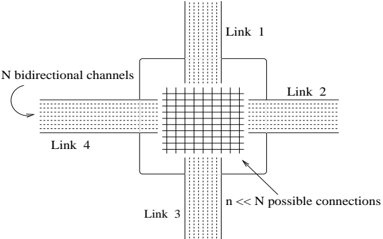
The diagram illustrates a network architecture featuring a central processing unit (grid) connected to four peripheral links (Link 1–4) via bidirectional communication channels. A key annotation highlights a relationship between the central grid and "n << N possible connections," suggesting a multiplexing or resource-sharing mechanism.
### Components/Axes
- **Central Grid**: Labeled "N bidirectional channels," depicted as a matrix of interconnected nodes.
- **Links**: Four labeled connections:
- **Link 1**: Positioned at the top, connected to the grid via dotted lines.
- **Link 2**: Positioned at the right, connected to the grid via dotted lines.
- **Link 3**: Positioned at the bottom, connected to the grid via dotted lines.
- **Link 4**: Positioned at the left, connected to the grid via dotted lines.
- **Annotation**: An arrow points from the central grid to the text "n << N possible connections," emphasizing a quantitative relationship.
### Content Details
- **Links**: All links are uniformly represented with dotted-line connections to the central grid, indicating bidirectional data flow.
- **Central Grid**: The grid’s internal structure is abstracted as a matrix, with no explicit numerical values provided.
- **Annotation**: The text "n << N possible connections" is explicitly tied to the central grid via an arrow, suggesting a constraint or optimization parameter.
### Key Observations
1. **Symmetry**: Links 1–4 are evenly distributed around the central grid, implying equal capacity or role in the architecture.
2. **Annotation Significance**: The inequality "n << N" indicates that the number of active connections (n) is orders of magnitude smaller than the total available channels (N), likely to highlight efficiency or scalability.
3. **Flow Direction**: All links feed into the central grid, which then distributes connections to "n << N" endpoints, suggesting a centralized control or aggregation point.
### Interpretation
The diagram represents a network topology where multiple links (Link 1–4) converge on a central processing unit (grid) with N bidirectional channels. The annotation "n << N possible connections" implies that the system dynamically selects a small subset (n) of the total channels (N) for active use, optimizing resource utilization. This could reflect:
- **Multiplexing**: Time- or frequency-division multiplexing to share channels among links.
- **Load Balancing**: Prioritizing connections to avoid congestion.
- **Scalability**: Designing for future expansion (N) while maintaining current efficiency (n).
The absence of numerical values for N or n leaves the exact ratio undefined, but the notation "<<" universally denotes a significant disparity, emphasizing the system’s efficiency. The bidirectional nature of channels suggests full-duplex communication, critical for real-time or high-throughput applications.