## Diagram: Network Switch
### Overview
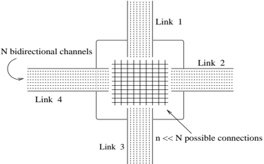
The image is a diagram of a network switch with four links, illustrating the concept of bidirectional channels and possible connections.
### Components/Axes
* **Links:** There are four links labeled Link 1, Link 2, Link 3, and Link 4, arranged in a cross shape.
* **Channels:** Each link is represented as having N bidirectional channels.
* **Switch Core:** The central part of the diagram represents the switch core, depicted as a grid.
* **Connections:** An arrow points to the switch core, indicating "n << N possible connections," meaning the number of possible connections within the switch is much smaller than the total number of channels.
### Detailed Analysis
* **Link 1:** Located at the top of the diagram.
* **Link 2:** Located on the right side of the diagram.
* **Link 3:** Located at the bottom of the diagram.
* **Link 4:** Located on the left side of the diagram.
* **Bidirectional Channels:** Each link is shown with multiple parallel lines, representing the N bidirectional channels.
* **Switch Core:** The grid in the center symbolizes the switch's ability to connect different channels from different links.
* **Connection Capacity:** The text "n << N possible connections" indicates that the switch has a limited number of simultaneous connections compared to the total number of channels available.
### Key Observations
* The diagram emphasizes the concept of a switch connecting multiple links.
* It highlights the idea of bidirectional channels within each link.
* The key point is that the number of possible connections within the switch is significantly less than the total number of channels.
### Interpretation
The diagram illustrates a simplified model of a network switch. The "N bidirectional channels" represent the capacity of each link, while the "n << N possible connections" highlights a key constraint in switch design: the number of simultaneous connections is limited by the switch's architecture and resources. This limitation is a fundamental aspect of network switch design, influencing performance and scalability. The diagram effectively conveys the basic principles of how a switch operates by connecting different links and managing data flow between them.