## Diagram: Agent Communication with Proxy
### Overview
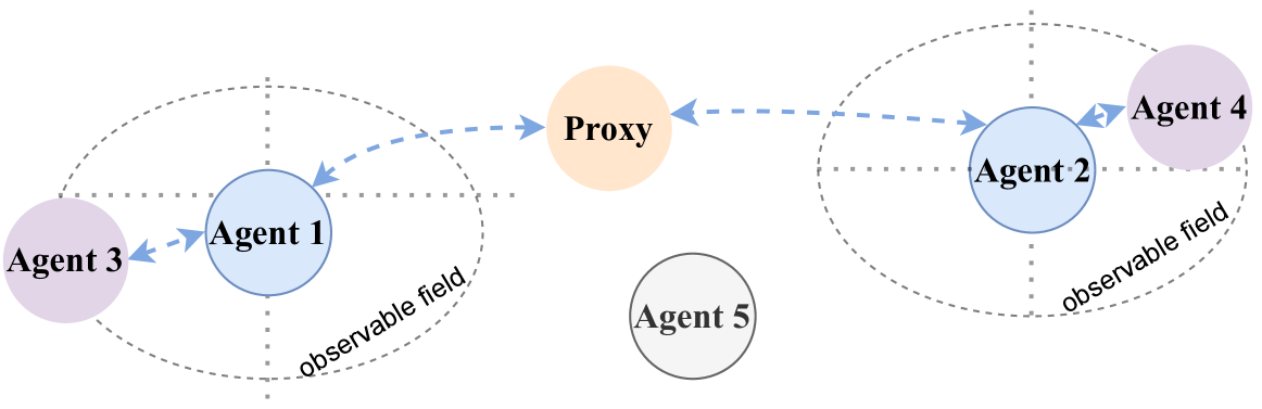
The image is a diagram illustrating communication between multiple agents, including a proxy. The agents are represented as circles, and the communication flow is indicated by dashed blue arrows. Some agents are within observable fields, represented by dotted gray circles.
### Components/Axes
* **Agents:** Agent 1 (light blue), Agent 2 (light blue), Agent 3 (light purple), Agent 4 (light purple), Agent 5 (gray).
* **Proxy:** Represented by a light orange circle.
* **Observable Field:** Represented by dotted gray circles around Agent 1/Agent 3 and Agent 2/Agent 4.
* **Communication Flow:** Represented by dashed blue arrows.
### Detailed Analysis
* **Agent 3** (light purple) communicates with **Agent 1** (light blue) via a dashed blue arrow.
* **Agent 1** (light blue) communicates with the **Proxy** (light orange) via a dashed blue arrow.
* The **Proxy** (light orange) communicates with **Agent 2** (light blue) via a dashed blue arrow.
* **Agent 2** (light blue) communicates with **Agent 4** (light purple) via a dashed blue arrow.
* **Agent 5** (gray) is isolated and does not communicate with any other agent or the proxy.
* **Observable Field 1:** Encompasses Agent 3 and Agent 1.
* **Observable Field 2:** Encompasses Agent 2 and Agent 4.
### Key Observations
* The communication flow is linear, starting from Agent 3, passing through Agent 1, the Proxy, Agent 2, and ending at Agent 4.
* Agent 5 is isolated and does not participate in the communication.
* Agents 3 and 4 are light purple, while Agents 1 and 2 are light blue. This may indicate different roles or groups.
* The Proxy acts as an intermediary between Agent 1 and Agent 2.
### Interpretation
The diagram illustrates a communication network where a proxy facilitates communication between two groups of agents. Agents 3 and 4 might represent external entities or data sources, while Agents 1 and 2 might be internal processing units. The observable fields suggest that Agents 3 and 1, as well as Agents 2 and 4, have some level of shared awareness or access to information. Agent 5's isolation could indicate a separate function or a state of inactivity. The use of a proxy suggests a need for controlled or mediated communication between the two groups of agents, possibly for security, data transformation, or protocol translation purposes.