## Flowchart: AI System Workflow with Adaptive Dependency and Failure Handling
### Overview
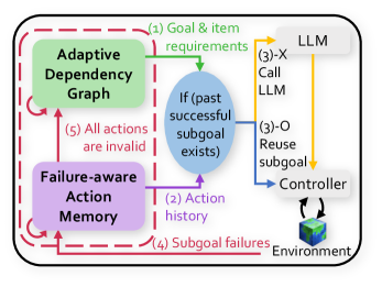
The diagram illustrates a cyclical AI system workflow involving goal processing, action memory, and failure recovery. Key components include an **Adaptive Dependency Graph**, **Failure-aware Action Memory**, **LLM (Large Language Model)**, **Controller**, and **Environment**. Arrows indicate data flow and decision logic, with color-coded paths (red, green, blue, yellow, purple) representing different stages or failure states.
---
### Components/Axes
1. **Adaptive Dependency Graph** (Green box, top-left):
- Represents dependencies between goals/items.
- Connected to LLM via step (1): "Goal & item requirements."
- Red dashed loop indicates invalid actions (step 5).
2. **Failure-aware Action Memory** (Purple box, bottom-left):
- Stores **Action History** (step 2).
- Handles **Subgoal Failures** (step 4).
- Red dashed loop for retry logic.
3. **LLM** (Gray box, top-right):
- Processes inputs via:
- **(3)-X Call LLM**: New subgoal generation.
- **(3)-O Reuse Subgoal**: Leverages past successes.
4. **Controller** (White box, center-right):
- Mediates between LLM and Environment.
- Receives output from LLM and sends commands to Environment.
5. **Environment** (3D cube icon, bottom-right):
- Represents the external system interacting with the Controller.
6. **Decision Logic** (Blue oval, center):
- Conditional check: "If (past successful subgoal exists)."
- Directs flow to reuse subgoals (step 3-O) or generate new ones (step 3-X).
---
### Detailed Analysis
- **Step 1**: The Adaptive Dependency Graph sends goal/item requirements to the LLM.
- **Step 2**: Action history is stored in Failure-aware Action Memory for reference.
- **Step 3**:
- If a past successful subgoal exists (blue oval), the LLM reuses it (3-O).
- Otherwise, the LLM generates a new subgoal (3-X).
- **Step 4**: Subgoal failures trigger feedback to the Failure-aware Action Memory.
- **Step 5**: If all actions are invalid, the system loops back to the Adaptive Dependency Graph.
**Color Coding**:
- Red: Failure paths (steps 4, 5).
- Green: Initial goal processing (step 1).
- Blue: Success-based reuse (step 3-O).
- Yellow: New subgoal generation (step 3-X).
- Purple: Memory-related processes (steps 2, 4).
---
### Key Observations
1. **Cyclical Workflow**: The system continuously adapts by reusing past successes or retrying after failures.
2. **Failure Handling**: Red loops emphasize robustness, ensuring the system avoids infinite invalid actions.
3. **Memory Integration**: Action history directly informs subgoal decisions, enabling learning from past experiences.
4. **LLM Centrality**: The LLM acts as the decision engine, balancing exploration (new subgoals) and exploitation (reuse).
---
### Interpretation
This diagram represents an **adaptive AI architecture** designed for dynamic environments. The **Adaptive Dependency Graph** ensures goals align with item capabilities, while the **Failure-aware Action Memory** prevents redundant failures by leveraging historical data. The LLM’s dual role (generating or reusing subgoals) optimizes efficiency, and the Controller-Environment loop enables real-world interaction. The red dashed loops highlight a critical safeguard: if no valid actions exist, the system resets dependencies to avoid stagnation.
The workflow prioritizes **efficiency** (reuse) and **resilience** (failure recovery), suggesting applications in robotics, autonomous systems, or complex task automation where adaptability is paramount. The absence of explicit numerical data implies a focus on logical flow rather than quantitative metrics.