\n
## Diagram: MicroBlaze Memory System Flow
### Overview
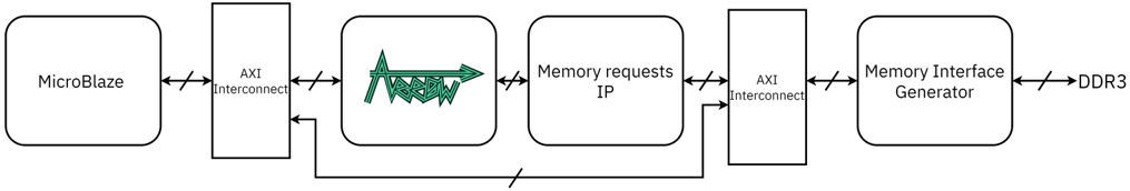
The image depicts a block diagram illustrating the flow of data within a MicroBlaze processor memory system. It shows the interaction between the MicroBlaze processor core, an AXI Interconnect, Memory Requests IP, another AXI Interconnect, a Memory Interface Generator, and DDR3 memory. The diagram emphasizes the data path and communication protocols used.
### Components/Axes
The diagram consists of the following components, arranged horizontally from left to right:
1. **MicroBlaze:** The processor core.
2. **AXI Interconnect (1):** A communication fabric connecting the MicroBlaze to the Memory Requests IP.
3. **Memory requests IP:** Handles memory requests. Contains a green arrow pattern.
4. **AXI Interconnect (2):** A communication fabric connecting the Memory Requests IP to the Memory Interface Generator.
5. **Memory Interface Generator:** Generates the interface to the DDR3 memory.
6. **DDR3:** The external dynamic random-access memory.
The connections between these components are represented by bidirectional arrows labeled "AXI Interconnect". A single bidirectional arrow connects the Memory Requests IP to the AXI Interconnect (2).
### Detailed Analysis or Content Details
The diagram shows a unidirectional flow of data represented by a green arrow pattern within the "Memory requests IP" block. This arrow points from left to right, suggesting a processing or forwarding of requests.
* **MicroBlaze to AXI Interconnect (1):** Bidirectional communication.
* **AXI Interconnect (1) to Memory requests IP:** Bidirectional communication.
* **Memory requests IP to AXI Interconnect (2):** Bidirectional communication.
* **AXI Interconnect (2) to Memory Interface Generator:** Bidirectional communication.
* **Memory Interface Generator to DDR3:** Bidirectional communication.
* **Memory requests IP to AXI Interconnect (2):** Bidirectional communication (indicated by a separate arrow).
There are no numerical values or specific data points present in the diagram. It is a conceptual representation of the system architecture.
### Key Observations
The diagram highlights the role of the AXI Interconnect as a central communication hub. The Memory Requests IP appears to be a key component in managing and processing memory requests. The bidirectional arrows indicate two-way communication between the components, allowing for both request and response data transfer. The green arrow within the Memory Requests IP suggests a specific processing step or data flow within that module.
### Interpretation
This diagram illustrates a typical memory system architecture for a MicroBlaze processor. The AXI Interconnects provide a flexible and scalable communication infrastructure. The Memory Requests IP likely performs address translation, memory management, and potentially caching functions. The Memory Interface Generator adapts the AXI protocol to the specific requirements of the DDR3 memory interface.
The diagram suggests a streamlined data flow from the processor core to the external memory. The bidirectional communication paths allow for efficient data transfer and control signaling. The presence of the Memory Requests IP indicates a level of abstraction and control over memory access, which is crucial for system performance and reliability. The green arrow within the Memory Requests IP could represent a specific optimization or data processing step within that module, such as request prioritization or reordering.
The diagram is a high-level overview and does not provide details about the internal workings of each component. It serves as a useful starting point for understanding the overall system architecture and data flow.