\n
## Diagram: Dataflow for Neural Network Optimization
### Overview
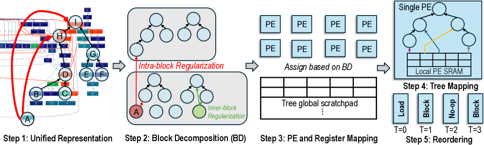
This diagram illustrates a five-step process for optimizing neural network execution, focusing on block decomposition, parallel execution unit (PE) mapping, and data reordering. The process begins with a unified representation of the network and culminates in optimized data access patterns for a local PE SRAM.
### Components/Axes
The diagram is divided into five sequential steps, labeled "Step 1" through "Step 5". Each step is visually represented with a corresponding diagram. Key elements include:
* **Step 1: Unified Representation:** Shows a grid-like structure with nodes labeled A through H, connected by red arcs.
* **Step 2: Block Decomposition (BD):** Displays a series of tree-like structures within light blue boxes, with some nodes highlighted in red (A) and green. The text "Intra-block Regularization" and "Inner-block Regularization" are present.
* **Step 3: PE and Register Mapping:** Shows a grid of "PE" (Parallel Execution) units and a table labeled "Tree global scratchpad". The text "Assign based on BD" is present.
* **Step 4: Tree Mapping:** Illustrates a tree structure with connections to a "Local PE SRAM" represented as a grid.
* **Step 5: Reordering:** Displays a timeline with steps labeled T=0, T=1, T=2, and T=3, with corresponding actions: "Load", "No-op", and "Block".
### Detailed Analysis or Content Details
**Step 1: Unified Representation:**
* A grid of small squares representing data elements.
* Nodes A through H are marked on the grid.
* A red arc connects A to H, and another connects A to nodes B, C, D, E, F, and G.
**Step 2: Block Decomposition (BD):**
* Multiple tree-like structures are shown within light blue boxes.
* Node A is highlighted in red.
* A node is highlighted in green, labeled "Inner-block Regularization".
* The text "Intra-block Regularization" is present.
**Step 3: PE and Register Mapping:**
* A 3x2 grid of "PE" units is shown.
* A table labeled "Tree global scratchpad" is present, but its contents are not visible.
* The text "Assign based on BD" is present.
**Step 4: Tree Mapping:**
* A tree structure is shown, with connections to a grid representing "Local PE SRAM".
* A yellow arrow indicates data flow from a node in the tree to the SRAM.
**Step 5: Reordering:**
* A timeline with four steps: T=0, T=1, T=2, T=3.
* T=0: "Load"
* T=1: "No-op"
* T=2: "Block"
* T=3: "Block"
### Key Observations
* The process progressively decomposes the neural network representation into smaller blocks and maps them onto parallel execution units.
* Regularization techniques ("Intra-block Regularization", "Inner-block Regularization") are applied during block decomposition.
* Data reordering is performed to optimize access patterns for the local PE SRAM.
* The timeline in Step 5 suggests a sequence of operations: loading data, followed by block processing.
### Interpretation
This diagram outlines a methodology for optimizing neural network execution on parallel hardware. The initial "Unified Representation" likely represents the original network structure. The "Block Decomposition" step aims to divide the network into smaller, manageable blocks, potentially to exploit parallelism and reduce computational complexity. The "PE and Register Mapping" step assigns these blocks to individual processing elements (PEs) and allocates registers for data storage. The "Tree Mapping" step visualizes the mapping of the decomposed network onto the local SRAM of each PE, and the "Reordering" step optimizes data access patterns to minimize latency and maximize throughput. The use of regularization techniques suggests an attempt to improve the robustness and generalization ability of the network. The timeline indicates a phased execution strategy, starting with data loading and followed by block-wise processing. The overall goal is to accelerate neural network inference or training by leveraging parallel processing and optimized data management.