## Flowchart: Multi-Step Data Processing Architecture
### Overview
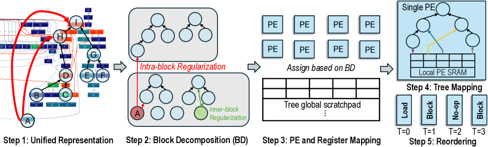
The image depicts a five-step computational architecture for processing data through hierarchical decomposition, parallel execution, and temporal reordering. It combines block-level optimization with register mapping and tree-based memory management.
### Components/Axes
1. **Step 1: Unified Representation**
- Nodes labeled A-I with colored connections (red, blue, green)
- Spatial arrangement: Circular nodes with bidirectional arrows
- Color coding:
- Red: Primary data flow
- Blue: Secondary dependencies
- Green: Control signals
2. **Step 2: Block Decomposition (BD)**
- Two sub-diagrams:
- **Top**: Hierarchical node connections (A-I) with red arrows
- **Bottom**: Regularization framework with:
- Red: Intra-block regularization
- Green: Inner-block regularization
- Node A highlighted in red
3. **Step 3: PE and Register Mapping**
- 2x2 grid of Processing Elements (PEs)
- "Tree global scratchpad" matrix with 4 columns
- Connection arrows from PEs to scratchpad
4. **Step 4: Tree Mapping**
- Single PE with local PE SRAM
- Tree structure with 4 nodes (Load, Block, No-op, Block)
- Temporal labels: T=0 to T=3
5. **Step 5: Reordering**
- Timeline visualization (T=0 to T=3)
- Color-coded operations:
- Blue: Load
- Red: Block
- Green: No-op
### Detailed Analysis
- **Step 1** establishes a unified data flow graph with 9 nodes and 12 connections
- **Step 2** introduces regularization constraints through color-coded arrows
- **Step 3** shows parallel processing elements (PEs) mapped to a global scratchpad
- **Step 4** demonstrates hierarchical data organization in a tree structure
- **Step 5** presents temporal optimization through operation reordering
### Key Observations
1. Color consistency: Red dominates control flow, green for optimization, blue for data
2. Temporal progression: Steps flow left-to-right with increasing complexity
3. Hierarchical structure: Single PE in Step 4 contrasts with multiple PEs in Step 3
4. Temporal granularity: 4 distinct time steps (T=0-3) in final stage
### Interpretation
This architecture demonstrates a multi-layered optimization strategy:
1. **Unified Representation** establishes foundational data relationships
2. **Block Decomposition** introduces spatial optimization through regularization
3. **PE Mapping** enables parallel processing while maintaining data locality
4. **Tree Mapping** organizes data hierarchically for efficient access
5. **Reordering** optimizes temporal execution through operation scheduling
The architecture suggests a hardware-software co-design approach, balancing parallelism (multiple PEs) with sequential optimization (temporal reordering). The use of color-coded regularization indicates a focus on maintaining data integrity during decomposition. The tree-based scratchpad implies a memory hierarchy optimized for both spatial and temporal locality.