## Circuit Diagrams: Control System and Op-Amp Configurations
### Overview
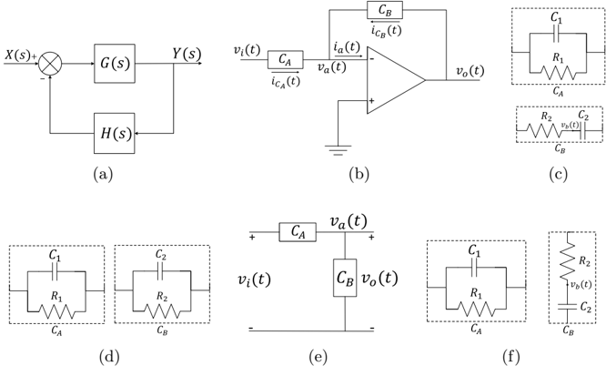
The image presents a collection of circuit diagrams and block diagrams related to control systems and operational amplifier (op-amp) configurations. It includes a feedback control system, an op-amp circuit with input and feedback components, and several variations of RC circuits.
### Components/Axes
* **(a) Feedback Control System:**
* **X(s):** Input signal
* **Y(s):** Output signal
* **G(s):** Forward path transfer function
* **H(s):** Feedback path transfer function
* Summing junction with positive and negative inputs.
* **(b) Op-Amp Circuit:**
* **v<sub>i</sub>(t):** Input voltage
* **v<sub>a</sub>(t):** Voltage at the inverting input of the op-amp
* **v<sub>o</sub>(t):** Output voltage
* **C<sub>A</sub>:** Input capacitor
* **i<sub>CA</sub>(t):** Current through C<sub>A</sub>
* **C<sub>B</sub>:** Feedback capacitor
* **i<sub>CB</sub>(t):** Current through C<sub>B</sub>
* Op-amp symbol with inverting (-) and non-inverting (+) inputs. The non-inverting input is grounded.
* **(c), (d), (e), (f) RC Circuits:**
* **R<sub>1</sub>, R<sub>2</sub>:** Resistors
* **C<sub>1</sub>, C<sub>2</sub>:** Capacitors
* **C<sub>A</sub>, C<sub>B</sub>:** Capacitors associated with circuit A and B respectively.
* **v<sub>b</sub>(t):** Voltage across the R2-C2 combination in (c) and (f).
* **v<sub>i</sub>(t):** Input voltage in (e).
* **v<sub>o</sub>(t):** Output voltage in (e).
* **v<sub>a</sub>(t):** Voltage at the junction of CA and CB in (e).
### Detailed Analysis or ### Content Details
* **(a) Feedback Control System:** A standard negative feedback control system is depicted. The input signal X(s) is compared with the feedback signal H(s) * Y(s). The error signal is then fed into the forward path transfer function G(s) to produce the output Y(s).
* **(b) Op-Amp Circuit:** An op-amp is configured with an input capacitor C<sub>A</sub> and a feedback capacitor C<sub>B</sub>. The input voltage v<sub>i</sub>(t) is applied through C<sub>A</sub> to the inverting input of the op-amp. The output voltage v<sub>o</sub>(t) is fed back through C<sub>B</sub> to the inverting input. The non-inverting input is grounded.
* **(c) RC Circuits:** Two parallel RC circuits are shown, labeled C<sub>A</sub> and C<sub>B</sub>. C<sub>A</sub> consists of a capacitor C<sub>1</sub> in parallel with a resistor R<sub>1</sub>. C<sub>B</sub> consists of a capacitor C<sub>2</sub> in series with a resistor R<sub>2</sub>, and the voltage across the R2-C2 combination is labeled v<sub>b</sub>(t).
* **(d) RC Circuits:** Two parallel RC circuits are shown in series, labeled C<sub>A</sub> and C<sub>B</sub>. C<sub>A</sub> consists of a capacitor C<sub>1</sub> in parallel with a resistor R<sub>1</sub>. C<sub>B</sub> consists of a capacitor C<sub>2</sub> in parallel with a resistor R<sub>2</sub>.
* **(e) RC Circuits:** A series RC circuit is shown, with C<sub>A</sub> in series with C<sub>B</sub>. C<sub>A</sub> is a capacitor, and C<sub>B</sub> is a capacitor. The input voltage v<sub>i</sub>(t) is applied to the series combination, and the output voltage v<sub>o</sub>(t) is taken across C<sub>B</sub>. The voltage at the junction of CA and CB is labeled v<sub>a</sub>(t).
* **(f) RC Circuits:** Two RC circuits are shown, labeled C<sub>A</sub> and C<sub>B</sub>. C<sub>A</sub> consists of a capacitor C<sub>1</sub> in parallel with a resistor R<sub>1</sub>. C<sub>B</sub> consists of a capacitor C<sub>2</sub> in series with a resistor R<sub>2</sub>, and the voltage across the R2-C2 combination is labeled v<sub>b</sub>(t).
### Key Observations
* The diagrams illustrate fundamental concepts in control systems and analog circuit design.
* The op-amp circuit in (b) likely represents an inverting amplifier configuration with capacitive input and feedback.
* The RC circuits in (c), (d), (e), and (f) demonstrate different arrangements of resistors and capacitors, which can be used for filtering, impedance matching, or other signal processing functions.
### Interpretation
The image provides a visual representation of basic control system principles and op-amp circuit configurations. The feedback control system demonstrates how negative feedback is used to regulate a system's output. The op-amp circuit shows how capacitors can be used to shape the frequency response of an amplifier. The RC circuits illustrate the versatility of resistors and capacitors in creating various signal processing functions. The different arrangements of resistors and capacitors in (c), (d), (e), and (f) would result in different frequency responses and impedance characteristics.