\n
## Diagram: Transconductance Amplifier Circuit Stages
### Overview
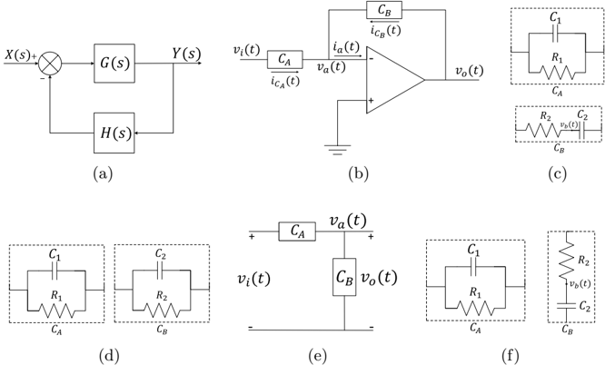
The image presents a series of diagrams illustrating the stages of a transconductance amplifier circuit. It begins with a block diagram of a feedback system and progresses through circuit representations involving operational amplifiers, capacitors, and resistors. The diagrams appear to demonstrate the equivalent circuits at different points in the signal processing chain.
### Components/Axes
The diagrams utilize the following components:
* **X(s):** Input signal.
* **Y(s):** Output signal.
* **G(s):** Transfer function of the forward path.
* **H(s):** Transfer function of the feedback path.
* **v<sub>i</sub>(t):** Input voltage.
* **v<sub>o</sub>(t):** Output voltage.
* **i<sub>C</sub>(t):** Collector current.
* **i<sub>CB</sub>(t):** Base current.
* **C<sub>1</sub>, C<sub>2</sub>:** Capacitors.
* **R<sub>1</sub>, R<sub>2</sub>:** Resistors.
* **C<sub>A</sub>, C<sub>B</sub>:** Capacitors.
* Operational Amplifier (triangle symbol).
* Ground symbol.
### Detailed Analysis or Content Details
**(a) Block Diagram:**
A block diagram showing a closed-loop system. The input signal X(s) is fed into a block representing the forward transfer function G(s). The output Y(s) is fed back to the input through a block representing the feedback transfer function H(s). A summation point (circle with a cross) combines the input signal and the feedback signal.
**(b) Operational Amplifier Circuit:**
An operational amplifier circuit with input voltage v<sub>i</sub>(t), collector current i<sub>C</sub>(t), base current i<sub>CB</sub>(t), and output voltage v<sub>o</sub>(t). The operational amplifier has a positive input connected to ground and a negative input connected to v<sub>i</sub>(t). The output is connected to a capacitor C<sub>B</sub>.
**(c) Equivalent Circuit 1:**
An equivalent circuit consisting of a capacitor C<sub>1</sub> in series with a resistor R<sub>1</sub>, connected to capacitor C<sub>A</sub>. This is in parallel with a resistor R<sub>2</sub> in series with a capacitor C<sub>B</sub>.
**(d) Equivalent Circuit 2:**
A circuit with C<sub>1</sub> and R<sub>1</sub> enclosed in a dashed box, and C<sub>2</sub> and R<sub>2</sub> enclosed in a dashed box. The two boxes are connected in series.
**(e) Simplified Circuit:**
A simplified circuit showing capacitors C<sub>A</sub> and C<sub>B</sub> connected in series between the input voltage v<sub>i</sub>(t) and the output voltage v<sub>o</sub>(t). A horizontal line is drawn beneath the capacitors.
**(f) Equivalent Circuit 3:**
An equivalent circuit consisting of a capacitor C<sub>1</sub> in series with a resistor R<sub>1</sub>, connected to capacitor C<sub>A</sub>. This is in parallel with a resistor R<sub>2</sub> in series with a capacitor C<sub>2</sub>, connected to capacitor C<sub>B</sub>. The output voltage v<sub>o</sub>(t) is taken across the parallel combination.
### Key Observations
The diagrams progressively simplify the circuit, moving from a block diagram to equivalent circuits. The presence of capacitors and resistors suggests frequency-dependent behavior. The operational amplifier in diagram (b) indicates a gain stage. The dashed boxes in diagram (d) may represent simplified models of specific circuit sections.
### Interpretation
The series of diagrams likely illustrates the derivation of an equivalent circuit model for a transconductance amplifier. The initial block diagram (a) establishes the overall system architecture. Diagram (b) shows the basic operational amplifier configuration. Diagrams (c), (d), (e), and (f) then present increasingly simplified equivalent circuits, likely obtained through circuit analysis techniques such as impedance transformation or approximation. The goal is to represent the amplifier's behavior with a manageable circuit model that can be used for further analysis and design. The simplification process suggests that certain circuit elements or effects are being neglected to achieve a more concise representation. The presence of capacitors indicates that the amplifier's performance is frequency-dependent, and the equivalent circuits are likely valid only within a specific frequency range. The diagrams demonstrate a systematic approach to circuit modeling, starting from a detailed representation and progressively simplifying it to obtain a more abstract but useful model.