# Technical Document Extraction: Machine Learning Training Recovery Process
This document provides a detailed technical breakdown of the provided diagram, which illustrates a checkpointing and recovery workflow for a machine learning training process.
## 1. Component Isolation
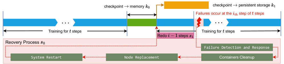
The image is divided into two primary horizontal regions:
* **Upper Region (Timeline):** A linear progression of training steps, checkpointing events, and failure occurrences.
* **Lower Region (Recovery Process $s_0$):** A detailed sub-process triggered by a system failure, contained within a light pink shaded box.
---
## 2. Timeline and Training Flow (Upper Region)
The timeline progresses from left to right, representing the sequential execution of training steps.
### Training Phases
* **Initial Training:** Represented by blue chevron bars.
* **Label:** "Training for $t$ steps"
* **Visual Note:** Includes an ellipsis (`...`) indicating a continuous sequence of steps.
* **Checkpointing to Memory ($k_0$):**
* **Color:** Green block.
* **Label:** "checkpoint $\rightarrow$ memory $k_0$"
* **Duration:** Indicated by a double-headed black arrow above the green block.
* **Checkpointing to Persistent Storage ($k_1$):**
* **Color:** Orange block (positioned above the main timeline).
* **Label:** "checkpoint $\rightarrow$ persistent storage $k_1$"
* **Flow:** An orange arrow points from the end of the memory checkpoint ($k_0$) to the start of the persistent storage checkpoint ($k_1$).
* **Post-Checkpoint Training:** Training resumes (blue bar) until a failure occurs.
* **Failure Event:**
* **Visual:** A red jagged "lightning bolt" icon.
* **Label (Red Text):** "Failures occur at the $i_{th}$ step of $t$ steps"
* **Redo Phase:**
* **Color:** Pink block below the blue training bar.
* **Label:** "Redo $i - 1$ steps $s_1$"
* **Logic:** Following a failure at step $i$, the system must re-execute the preceding $i-1$ steps from the last valid checkpoint.
* **Resumed Training:**
* **Label:** "Training for $t$ steps" (following the redo phase).
---
## 3. Recovery Process $s_0$ (Lower Region)
When a failure occurs, the system enters a recovery cycle. This is depicted inside a light pink box labeled **"Recovery Process $s_0$"**.
### Workflow Components
The recovery process consists of four sequential stages, represented by dark green rectangular blocks with white monospaced text. The flow is indicated by red dotted arrows moving from right to left.
1. **Failure Detection and Response:**
* Triggered directly by the failure event (indicated by a red dotted line from the failure icon).
2. **Containers Cleanup:**
* The next step after detection, ensuring the environment is cleared of stale processes.
3. **Node Replacement:**
* The process of replacing faulty hardware or virtual instances.
4. **System Restart:**
* The final stage of the recovery process.
* **Flow Completion:** A red dotted line leads from "System Restart" back up to the start of the "Redo $i - 1$ steps $s_1$" phase in the timeline.
---
## 4. Summary of Variables and Symbols
| Symbol | Description |
| :--- | :--- |
| $t$ | Total number of steps in a training interval. |
| $k_0$ | Time/cost associated with checkpointing to volatile memory. |
| $k_1$ | Time/cost associated with checkpointing to persistent storage. |
| $i$ | The specific step index where a failure occurs. |
| $s_0$ | The total time/process for system recovery (Detection $\rightarrow$ Restart). |
| $s_1$ | The time/process for re-executing steps lost due to failure. |
## 5. Technical Logic Summary
The diagram describes a fault-tolerant training system. Training proceeds in blocks of $t$ steps. At the end of a block, a two-stage checkpoint is performed: first to fast memory ($k_0$), then to durable persistent storage ($k_1$). If a failure occurs at step $i$, the system must undergo a multi-stage recovery process ($s_0$) involving cleanup and hardware replacement, followed by a re-computation phase ($s_1$) to return to the state exactly before the failure occurred.