# Technical Document Extraction: System Training and Recovery Workflow
## Diagram Overview
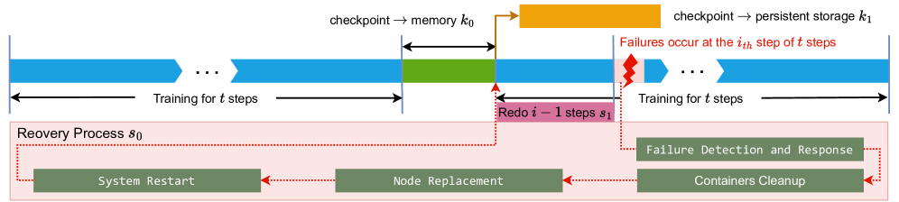
This flowchart illustrates a distributed training and recovery workflow with checkpointing, failure handling, and system restoration processes. The diagram uses color-coded components to represent different stages and actions.
---
## Key Components and Flow
### 1. Training Process (Top Section)
- **Blue Arrows**: Represent training iterations
- "Training for t steps" (repeated twice)
- **Green Section**: Checkpointing mechanism
- "checkpoint → memory k₀" (temporary storage)
- "checkpoint → persistent storage k₁" (long-term storage)
- **Orange Arrow**: Data transfer between memory and persistent storage
- **Failure Indicator**: Red lightning bolt
- "Failures occur at the iₜᵐ step of t steps"
### 2. Recovery Process (Bottom Section)
- **Pink Box**: "Recovery Process s₀" (overall recovery workflow)
- **Green Rectangles**: Recovery steps
1. "System Restart" (initial recovery action)
2. "Node Replacement" (hardware/software restoration)
3. "Containers Cleanup" (environment sanitization)
- **Red Dotted Arrow**: Rollback mechanism
- "Rede i - 1 steps s₁" (reverting to previous state)
### 3. Failure Handling
- **Red Lightning Bolt**: Visual indicator of failure occurrence
- **Dashed Red Arrows**: Connect failure point to recovery process
- **Text Labels**:
- "Failure Detection and Response"
- "Containers Cleanup"
---
## Color Coding Legend
While no explicit legend is present, the following color associations are used:
- **Blue**: Training phases
- **Green**: Checkpointing/storage
- **Orange**: Data transfer
- **Pink**: Recovery process
- **Red**: Failure indicators and rollback
---
## Spatial Grounding
- **Top Section**: Training workflow (horizontal timeline)
- **Bottom Section**: Recovery workflow (horizontal timeline)
- **Central Connection**: Vertical dashed lines link training and recovery processes
---
## Process Flow Description
1. **Training Phase**:
- System trains for t steps (blue arrow)
- Checkpoint saved to memory (k₀) and persistent storage (k₁)
2. **Failure Event**:
- Failure occurs at iₜᵐ step (red lightning bolt)
3. **Recovery Phase**:
- System restarts (green rectangle)
- Nodes replaced (green rectangle)
- Containers cleaned (green rectangle)
- Rollback to previous checkpoint (red dotted arrow to "Rede i - 1 steps s₁")
---
## Technical Notes
- No numerical data or quantitative metrics are present
- All components are labeled with descriptive text
- Diagram uses directional arrows to indicate process flow
- Color coding serves as implicit legend for component categorization
This diagram emphasizes fault tolerance mechanisms in distributed training systems, showing how failures are detected, contained, and recovered from using checkpointing and rollback procedures.