## Diagram: Coordinate System with Velocity Vectors and Right Ear Reference
### Overview
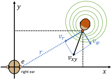
The diagram illustrates a 2D coordinate system (x, y) with a reference point labeled "right ear" at the origin (0,0). A secondary point labeled "e" is positioned along the x-axis. A third point (unlabeled) is shown with three velocity vectors emanating from it: radial velocity **v<sub>r</sub>**, tangential velocity **v<sub>φ</sub>**, and vertical velocity **v<sub>xy</sub>**. Concentric green circles around this point suggest a wavefront or field propagation.
### Components/Axes
- **Axes**:
- Horizontal axis labeled **x** (rightward).
- Vertical axis labeled **y** (upward).
- **Key Labels**:
- "right ear" at the origin (intersection of x and y axes).
- Point **e** on the x-axis (exact coordinate unspecified).
- Velocity vectors: **v<sub>r</sub>** (radial, outward), **v<sub>φ</sub>** (tangential, counterclockwise), **v<sub>xy</sub>** (vertical, downward).
- **Visual Elements**:
- Dotted blue lines connecting the origin to the point with velocity vectors.
- Concentric green circles around the velocity point, implying radial symmetry or wave propagation.
### Detailed Analysis
- **Coordinate System**:
- The origin (0,0) is explicitly labeled as the "right ear," establishing a reference point for spatial measurements.
- Point **e** lies on the x-axis but lacks a numerical coordinate (position unspecified).
- **Velocity Vectors**:
- **v<sub>r</sub>**: Radial component, directed outward from the velocity point along the line connecting it to the origin.
- **v<sub>φ</sub>**: Tangential component, perpendicular to **v<sub>r</sub>**, suggesting rotational motion.
- **v<sub>xy</sub>**: Vertical component, directed downward along the y-axis.
- **Concentric Circles**:
- Green circles centered at the velocity point indicate a field or wavefront propagating outward. No numerical scale or units are provided.
### Key Observations
1. **Orthogonal Decomposition**: The velocity vectors (**v<sub>r</sub>**, **v<sub>φ</sub>**, **v<sub>xy</sub>**) are orthogonal, consistent with polar-to-Cartesian coordinate transformations.
2. **Reference Point**: The "right ear" at the origin implies this system may model spatial relationships relative to an auditory or anatomical reference.
3. **Wavefront Implication**: The concentric circles suggest the velocity point is a source of waves (e.g., sound, pressure), with **v<sub>r</sub>** and **v<sub>φ</sub>** describing motion in the wave's propagation direction.
### Interpretation
This diagram likely models **velocity decomposition in a polar-Cartesian hybrid system**, with the "right ear" serving as a fixed reference. The velocity point's motion is resolved into:
- **Radial velocity (v<sub>r</sub>)**: Motion directly away from the origin.
- **Tangential velocity (v<sub>φ</sub>)**: Motion perpendicular to the radial direction, implying rotational dynamics.
- **Vertical velocity (v<sub>xy</sub>)**: Motion along the y-axis, independent of the radial-tangential plane.
The concentric circles reinforce the idea of wave propagation or field influence originating from the velocity point. The absence of numerical values or units limits quantitative analysis, but the geometric relationships emphasize the interplay between linear and rotational motion in a 2D space. The "right ear" reference suggests applications in auditory modeling, spatial navigation, or biomechanical systems where directional motion relative to a fixed anatomical point is critical.