\n
## Diagram: Binaural Hearing Model
### Overview
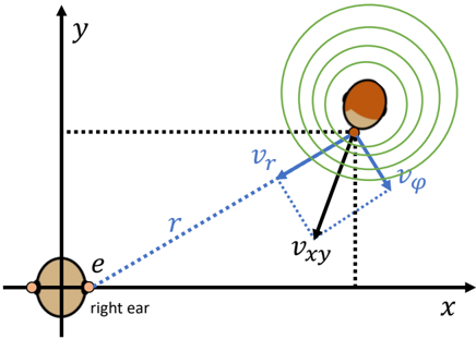
The image is a 2D diagram illustrating a model of binaural hearing, focusing on how sound waves reach the ears and are processed. It depicts a head in profile with a sound source emitting circular waves, and vectors representing sound velocity components. The diagram uses a Cartesian coordinate system (x, y) to define spatial relationships.
### Components/Axes
* **Axes:** The diagram utilizes a Cartesian coordinate system with the x-axis horizontal and the y-axis vertical.
* **Head:** A brown silhouette represents the head in profile.
* **Ears:** Two circular shapes represent the ears. The ear on the left is labeled "right ear".
* **Sound Source:** Concentric green circles emanating from a point near the head represent sound waves.
* **Vectors:** Three vectors originate from the sound source:
* `r`: A dashed blue vector pointing from the sound source to the "right ear".
* `v_r`: A solid blue vector.
* `v_xy`: A solid black vector.
* `v_φ`: A solid blue vector.
### Detailed Analysis
The diagram shows the following spatial relationships and components:
* **Sound Waves:** The concentric circles indicate that the sound source is emitting waves that propagate outwards in all directions.
* **Ear Position:** The "right ear" is positioned on the negative x-axis.
* **Vector `r`:** This vector represents the distance between the sound source and the "right ear". Its length is approximately 2.5 units on the x-axis.
* **Vector `v_r`:** This vector points approximately towards the "right ear" and is angled slightly upwards. Its length is approximately 1.0 units.
* **Vector `v_xy`:** This vector points downwards and to the left. Its length is approximately 0.7 units.
* **Vector `v_φ`:** This vector points approximately upwards and to the right. Its length is approximately 0.5 units.
* **Angle:** The angle between `v_r` and `v_φ` appears to be approximately 90 degrees.
* **Coordinate System:** The origin (0,0) is located at the center of the diagram.
### Key Observations
* The diagram illustrates the decomposition of sound velocity into radial (`v_r`) and tangential (`v_φ`) components.
* The vector `v_xy` appears to represent a component of the sound velocity perpendicular to the line connecting the sound source and the ear.
* The diagram is a simplified model and does not account for factors such as head shape, ear canal geometry, or sound reflection.
### Interpretation
This diagram likely represents a simplified model used to explain how humans localize sound sources using binaural cues. The difference in arrival time and intensity of sound at the two ears (Interaural Time Difference - ITD and Interaural Level Difference - ILD) are key factors in sound localization. The vectors `v_r`, `v_xy`, and `v_φ` likely represent components of the sound velocity that contribute to these binaural cues. The radial component (`v_r`) represents the direct path from the source to the ear, while the other components represent the effects of sound diffraction and reflection around the head. The diagram suggests that the brain processes these components to determine the direction of the sound source. The use of a coordinate system allows for a quantitative analysis of these relationships.