## System Architecture Diagram: FPGA-Based Deep Learning Workflow
### Overview
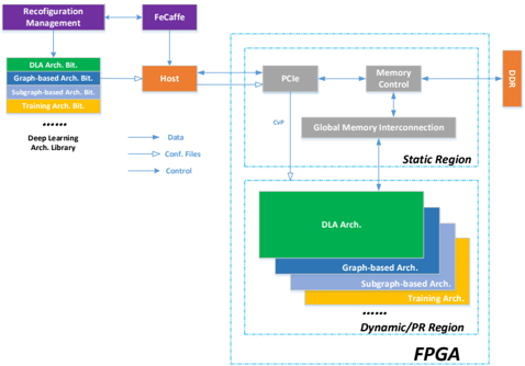
The diagram illustrates a hierarchical system architecture for FPGA-based deep learning, emphasizing reconfiguration management, data flow, and memory control. It divides the system into **Static Region** (hardware components) and **Dynamic/PR Region** (software architectures), with bidirectional interactions between them.
### Components/Axes
- **Key Components**:
- **Reconfiguration Management** (purple box)
- **FeCaffe** (purple box)
- **Host** (orange box)
- **PCIe** (gray box)
- **Memory Control** (gray box)
- **DDR** (orange box)
- **Global Memory Interconnection** (gray box)
- **Architecture Bits** (color-coded):
- **DLA Arch. Bit** (green)
- **Graph-based Arch. Bit** (blue)
- **Subgraph-based Arch. Bit** (light blue)
- **Training Arch. Bit** (orange)
- **Data Flow Arrows**:
- **Data** (blue arrows)
- **Config. Files** (blue arrows)
- **Control** (blue arrows)
### Detailed Analysis
1. **Static Region**:
- Contains **PCIe**, **Memory Control**, and **DDR**.
- **PCIe** connects to **Host** and **Memory Control**.
- **Memory Control** links to **Global Memory Interconnection** and **DDR**.
- **DDR** is the endpoint for data flow.
2. **Dynamic/PR Region**:
- Includes **DLA Arch.**, **Graph-based Arch.**, **Subgraph-based Arch.**, and **Training Arch.**.
- These architectures are nested hierarchically, with **DLA Arch.** as the largest (green) and **Training Arch.** as the smallest (orange).
3. **Control Flow**:
- **Reconfiguration Management** feeds into **FeCaffe**, which connects to **Host**.
- **Host** distributes **Data**, **Config. Files**, and **Control** to the **Dynamic/PR Region**.
- **Global Memory Interconnection** bridges the **Static** and **Dynamic** regions.
4. **Color Legend**:
- **Green**: DLA Arch. Bit
- **Blue**: Graph-based Arch. Bit
- **Light Blue**: Subgraph-based Arch. Bit
- **Orange**: Training Arch. Bit
- **Purple**: Reconfiguration Management/FeCaffe
- **Orange**: Host/DDR
### Key Observations
- **Hierarchical Structure**: The system separates hardware (Static) and software (Dynamic) layers, with clear demarcation.
- **Data Flow**: Data originates from the **Deep Learning Arch. Library**, flows through **Host**, and is processed via **PCIe** and **Memory Control** before reaching **DDR**.
- **Reconfiguration**: **FeCaffe** and **Reconfiguration Management** suggest dynamic adaptation of architectures during runtime.
- **Memory Management**: **Global Memory Interconnection** implies shared memory access between static and dynamic regions.
### Interpretation
This diagram represents an FPGA-based deep learning system optimized for flexibility and efficiency. The **Static Region** handles hardware-level operations (e.g., PCIe communication, memory allocation), while the **Dynamic/PR Region** manages adaptive software architectures (e.g., DLA, graph-based models). The bidirectional arrows indicate that reconfiguration (via **FeCaffe**) and control signals dynamically adjust the system’s behavior, enabling real-time optimization of deep learning tasks. The use of color-coded architecture bits highlights modularity, allowing selective activation of specific computational units (e.g., graph-based vs. subgraph-based processing). The integration of **Global Memory Interconnection** suggests a unified memory pool, critical for high-throughput applications.
**Notable Trends**:
- The **DLA Arch.** dominates the Dynamic Region, implying it is the primary architecture for deep learning tasks.
- **Training Arch.** is the smallest, suggesting it is used for lightweight or specialized training workflows.
- **DDR** acts as the final data sink, emphasizing its role in persistent storage or offloading.
**Underlying Logic**:
The system prioritizes reconfigurability (via **FeCaffe**) and modularity (via architecture bits), enabling FPGAs to adapt to diverse deep learning workloads without hardware redesign. The separation of static and dynamic regions ensures stability in hardware operations while allowing software flexibility.