## Diagram: Schematic Representation of a Pressurized Cylinder
### Overview
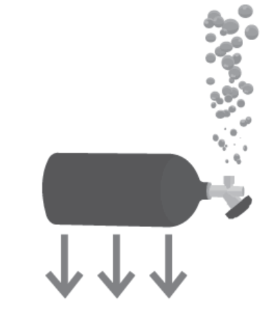
The image is a minimalist, monochromatic vector-style diagram depicting a horizontal, dark grey cylindrical tank. The diagram illustrates two distinct physical phenomena simultaneously: the release of gas (represented by rising bubbles) and the application of a downward force (represented by downward-pointing arrows). There is no text or numerical data present in the image.
### Components
* **Cylinder Body:** A solid, dark grey horizontal cylinder representing a pressurized vessel or tank.
* **Valve Assembly:** A stylized nozzle located at the right-hand end of the cylinder, angled slightly downwards.
* **Bubbles:** A cluster of grey, circular shapes of varying sizes, originating from the valve and extending vertically upwards.
* **Force Vectors:** Three identical, grey, downward-pointing arrows positioned directly beneath the main body of the cylinder.
### Detailed Analysis
* **Cylinder Positioning:** The cylinder is the central element, oriented horizontally.
* **Bubble Dynamics (Top-Right):** A stream of bubbles rises vertically from the valve assembly. The bubbles are circular, with sizes ranging from approximately 5% to 15% of the cylinder's diameter. The density of the bubbles is higher near the valve and becomes more sparse as they rise, suggesting a continuous venting or leakage process.
* **Force Vectors (Bottom):** Three arrows are positioned below the cylinder body. They are evenly spaced along the length of the cylinder. These arrows point straight down, indicating a downward force vector, such as gravity or weight.
* **Spatial Relationship:** The diagram creates a visual contrast between the upward movement of the gas (bubbles) and the downward force (arrows) acting upon the object.
### Key Observations
* **Lack of Text:** The diagram relies entirely on visual symbolism; no labels, units, or legends are provided.
* **Visual Contrast:** The diagram juxtaposes an upward-moving phenomenon (gas release) with a downward-moving force (gravity/weight).
* **Stylization:** The image uses a flat, iconographic style, typical of technical manuals or safety signage.
### Interpretation
This diagram likely serves as a conceptual illustration for a technical or safety context involving pressurized gas cylinders.
* **Gas Release/Leakage:** The bubbles clearly indicate that the cylinder is venting gas or leaking. This could represent a decompression event, a safety relief valve opening, or a damaged container.
* **Downward Force:** The arrows pointing downward likely represent the weight of the cylinder (gravity) or a downward force being applied to the object.
* **Synthesis:** The combination of these elements suggests a scenario where a heavy, pressurized object is being acted upon by external forces while simultaneously losing internal pressure. In a practical engineering or safety context, this could be an icon representing "Heavy Pressurized Cylinder" or a warning diagram illustrating the dangers of a leaking tank under load. Without further context, it is a schematic representation of a pressurized vessel undergoing both mass-related force and gas discharge.