## Diagram: Gas Cylinder Release Mechanism
### Overview
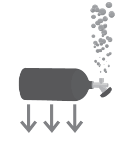
The image depicts a simplified grayscale diagram of a cylindrical gas cylinder with a valve assembly. Bubbles are illustrated rising from the valve, and three downward-pointing arrows are positioned below the cylinder. No textual labels, legends, or numerical data are present.
### Components/Axes
- **Primary Elements**:
- **Cylinder**: A horizontal, dark gray cylindrical tank with rounded ends.
- **Valve Assembly**: A metallic valve with a lever mechanism attached to the cylinder’s right end.
- **Bubbles**: Multiple gray spheres ascending vertically from the valve, suggesting gas release.
- **Arrows**: Three identical downward-pointing arrows aligned horizontally below the cylinder.
- **Spatial Relationships**:
- The valve is positioned at the cylinder’s right terminus.
- Bubbles originate directly from the valve and ascend in a dispersed pattern.
- Arrows are equidistant and parallel, located beneath the cylinder’s base.
### Detailed Analysis
- **Valve and Gas Flow**:
The valve’s lever is oriented horizontally, implying an open state. The ascending bubbles indicate gas escaping under pressure. No numerical pressure or flow rate values are provided.
- **Arrows**:
The three downward arrows lack labels or annotations. Their placement and direction suggest a force or flow direction (e.g., gravitational pull, downward gas movement, or structural support).
- **Absence of Textual Data**:
No labels, legends, or axis markers are visible. The diagram relies solely on visual symbolism.
### Key Observations
1. **Unidirectional Flow**: Gas release is depicted as a singular upward trajectory from the valve.
2. **Ambiguous Arrows**: The purpose of the downward arrows is unclear without contextual labels.
3. **Simplified Representation**: The diagram omits technical details (e.g., pressure gauges, safety mechanisms).
### Interpretation
The diagram likely illustrates a conceptual model of gas release from a pressurized cylinder. The upward bubbles emphasize the physical behavior of gas escaping into a less dense medium (e.g., air). The downward arrows may imply:
- **Gravitational Influence**: Gas density causing downward movement post-release (contradicting the bubbles’ ascent).
- **Structural Support**: Indicating the cylinder’s anchoring mechanism.
- **Flow Direction**: A secondary pathway for gas or liquid (e.g., liquid propellant in a gas cylinder).
The lack of textual data limits quantitative analysis. The diagram prioritizes symbolic representation over technical precision, making it suitable for educational or conceptual contexts rather than engineering specifications.