## Diagram: Neural Network Processing Pipeline for Image Classification
### Overview
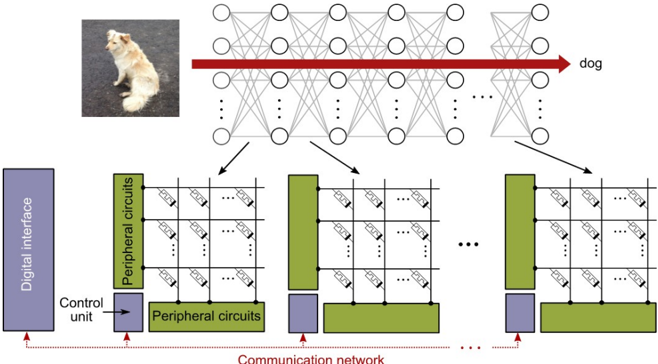
The diagram illustrates a technical system for image classification using a neural network architecture. It shows the flow of data from a digital interface through peripheral circuits, a communication network, and finally into a multi-layered neural network that outputs a classification label ("dog"). The system emphasizes modular processing stages with distinct color-coded components.
### Components/Axes
1. **Digital Interface** (Purple block on the far left)
- Represents the input source for raw image data
2. **Control Unit** (Small purple block below digital interface)
- Coordinates processing between components
3. **Peripheral Circuits** (Green grid structures)
- Multiple identical modules arranged in rows
- Labeled with "Peripheral circuits" text
4. **Communication Network** (Dashed red lines connecting components)
- Connects peripheral circuits to neural network
5. **Neural Network** (Central interconnected node structure)
- Three distinct layers:
- Input layer (leftmost nodes)
- Hidden layers (middle interconnected nodes)
- Output layer (rightmost nodes)
- Final output labeled "dog" with red arrow
6. **Color Coding**
- Purple: Digital interface/control unit
- Green: Peripheral circuits
- Blue: Communication network elements
- Red: Final classification output
### Detailed Analysis
- **Input Processing**: Digital interface → Control unit → Peripheral circuits (grid structure suggests parallel processing)
- **Data Flow**:
- Peripheral circuits connect via communication network (dashed red lines) to neural network
- Neural network shows progressive complexity from input to output layers
- **Output**: Final node cluster outputs "dog" with directional arrow
- **Modular Design**: Repeating peripheral circuit patterns suggest scalable architecture
### Key Observations
1. The system employs a hierarchical processing approach with three distinct stages
2. Peripheral circuits appear to perform feature extraction before neural network processing
3. Communication network uses dashed lines, implying non-direct data transfer
4. Neural network visualization uses standard node-connection architecture
5. Color coding provides clear component differentiation without explicit legend
### Interpretation
This diagram represents a distributed computing architecture for image classification:
- **Peripheral circuits** likely handle preprocessing tasks (e.g., noise reduction, feature extraction)
- **Communication network** coordinates data between processing modules
- **Neural network** performs final pattern recognition and classification
- The red arrow emphasizing "dog" output highlights the system's purpose: transforming raw image data into semantic labels
- Modular design suggests potential for adding more peripheral circuits to handle larger datasets or more complex image types
- The absence of explicit timing indicators implies focus on architectural relationships rather than performance metrics