# Technical Document Extraction: Collaborative Workspace Diagram
## Diagram Overview
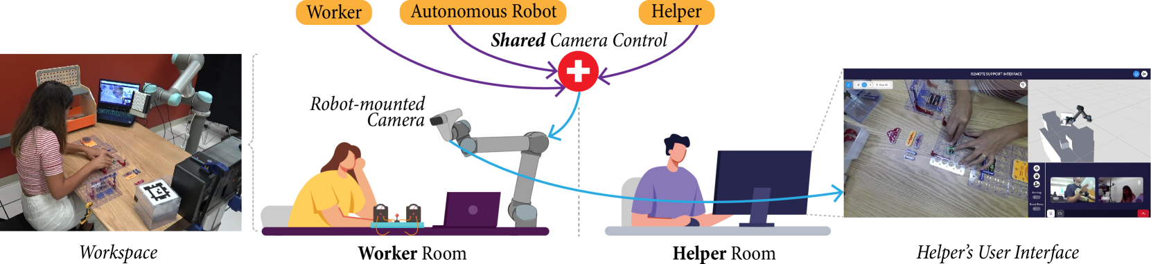
The image depicts a collaborative workspace system involving three primary entities: **Worker**, **Autonomous Robot**, and **Helper**. The system emphasizes **Shared Camera Control** and remote support capabilities.
---
### Key Components and Labels
1. **Workspace**
- A physical area where a worker interacts with tools and materials.
- Includes a **Robot-mounted Camera** (mounted on a robotic arm) and a **Laptop** displaying a live feed.
2. **Worker Room**
- Contains a **Worker** (illustrated as a seated individual) and a **Laptop**.
- The **Robot-mounted Camera** is positioned to capture the workspace.
3. **Helper Room**
- Features a **Helper** (illustrated as a seated individual) operating a **Computer Monitor**.
- The monitor displays a **Helper’s User Interface** with a split-screen view:
- **Live Feed**: Real-time video of the workspace.
- **3D Model**: A digital representation of the workspace and robot.
4. **Helper’s User Interface**
- Labeled **"REMOTE SUPPORT INTERFACE"** at the top.
- Includes interactive elements (e.g., buttons, sliders) for controlling the robot and camera.
---
### Flow and Interactions
1. **Shared Camera Control**
- Centralized system (marked with a red cross symbol) managing camera feeds.
- Receives input from the **Robot-mounted Camera** (blue arrow) and transmits data to the **Helper Room**.
2. **Data Flow**
- **Workspace → Worker Room**: Robot-mounted camera captures the workspace.
- **Worker Room → Helper Room**: Data is transmitted to the Helper’s interface.
- **Helper Room → Workspace**: The Helper can remotely control the robot via the interface.
---
### Textual Elements
- **Labels**:
- "Worker", "Autonomous Robot", "Helper" (top section).
- "Robot-mounted Camera", "Worker Room", "Helper Room", "Helper’s User Interface".
- "Shared Camera Control" (central hub).
- "REMOTE SUPPORT INTERFACE" (top of the Helper’s interface).
- **Arrows**:
- Purple arrows connect **Worker** and **Helper** to **Shared Camera Control**.
- Blue arrows indicate data flow between **Robot-mounted Camera** and **Helper Room**.
---
### Spatial Grounding
- **Legend**: Not explicitly present.
- **Color Coding**:
- **Blue**: Data flow arrows (e.g., robot camera to Helper Room).
- **Purple**: Control arrows (e.g., Worker/Helper to Shared Camera Control).
- **Red**: Cross symbol for Shared Camera Control.
---
### Component Isolation
1. **Header**:
- Labels for **Worker**, **Autonomous Robot**, and **Helper**.
- Central **Shared Camera Control** hub.
2. **Main Chart**:
- **Workspace**: Worker interacting with tools.
- **Worker Room**: Robot-mounted camera and Worker.
- **Helper Room**: Helper operating the interface.
3. **Footer**:
- **Helper’s User Interface**: Split-screen live feed and 3D model.
---
### Notes
- No numerical data, charts, or tables are present.
- All textual elements are in **English**.
- The diagram emphasizes remote collaboration and real-time monitoring via shared camera control.