## Security Diagram: Trusted Execution Environment (TEE)
### Overview
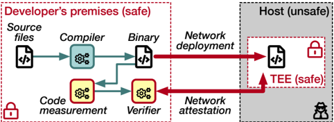
The image is a diagram illustrating a security model involving a Trusted Execution Environment (TEE). It contrasts a "Developer's premises (safe)" environment with a "Host (unsafe)" environment, showing the flow of code and processes between them, and highlighting the role of the TEE in maintaining security.
### Components/Axes
* **Environments:**
* Developer's premises (safe): Enclosed in a dashed red rectangle.
* Host (unsafe): Enclosed in a dashed black rectangle, with a gray fill.
* TEE (safe): Enclosed in a dashed red rectangle, within the "Host (unsafe)" environment.
* **Processes/Components within Developer's Premises:**
* Source files: Represented by a document icon with "</>" inside.
* Compiler: Represented by a blue gear icon within a rounded rectangle.
* Binary: Represented by a document icon with "</>" inside.
* Code measurement: Represented by a yellow gear icon within a rounded rectangle.
* Verifier: Represented by a yellow gear icon within a rounded rectangle.
* Network deployment: Text label.
* Network attestation: Text label.
* **Processes/Components within Host:**
* TEE: Represented by a document icon with "</>" inside.
* **Security Indicators:**
* Red padlock icon: Indicates a secure environment or process.
* Black hacker icon: Indicates an unsafe environment.
* **Arrows:**
* Blue arrows: Represent the flow of code/data within the "Developer's premises".
* Red arrows: Represent the flow of code/data between "Developer's premises" and "Host".
### Detailed Analysis
* **Developer's Premises (safe):**
* The process starts with "Source files".
* "Source files" are processed by the "Compiler", resulting in a "Binary".
* "Source files" are also processed by "Code measurement", and the result is sent to the "Verifier".
* The "Binary" is deployed to the "Host" via "Network deployment".
* The "Verifier" communicates with the "Host" via "Network attestation".
* A red padlock icon is present in the bottom-left corner, indicating a secure environment.
* **Host (unsafe):**
* The "Binary" is deployed to the "TEE (safe)" within the "Host".
* The "Verifier" attests to the "TEE (safe)" within the "Host".
* A red padlock icon is present within the "TEE (safe)", indicating a secure environment.
* A black hacker icon is present in the bottom-right corner, indicating an unsafe environment.
* **Flow of Data:**
* "Source files" -> "Compiler" -> "Binary" -> "Network deployment" -> "TEE (safe)"
* "Source files" -> "Code measurement" -> "Verifier" -> "Network attestation" -> "TEE (safe)"
### Key Observations
* The diagram highlights the contrast between a secure development environment and an insecure host environment.
* The TEE is presented as a secure enclave within the insecure host, protecting the "Binary" from potential threats.
* Code measurement and verification are used to ensure the integrity of the code running within the TEE.
* Network deployment and attestation are used to transfer and verify the code between the two environments.
### Interpretation
The diagram illustrates a security model where code developed in a trusted environment is deployed to an untrusted host. The Trusted Execution Environment (TEE) provides a secure enclave within the untrusted host, protecting the code from potential attacks. The code measurement and verification processes ensure that only trusted code is executed within the TEE. This model is commonly used in scenarios where sensitive data or operations need to be performed on untrusted platforms, such as mobile devices or cloud servers. The diagram emphasizes the importance of establishing a chain of trust from the development environment to the execution environment to ensure the security and integrity of the code.