\n
## Diagram: Barrel Shifter
### Overview
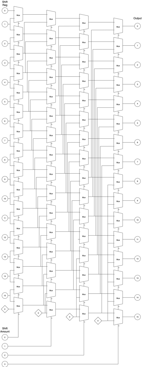
The image depicts a digital circuit diagram representing a barrel shifter. It consists of multiple multiplexers (labeled "Mux") arranged in a cascaded structure to perform bit shifting operations. The diagram shows a 16-bit input ("Shift Reg") and a 4-bit shift amount control ("Shift Amount"), producing a 16-bit output.
### Components/Axes
* **Shift Reg:** Input register with 16 bits, labeled 1 through 16 vertically on the left side.
* **Shift Amount:** Control input with 4 bits, labeled 0 through 3 vertically on the bottom left.
* **Mux:** Multiplexers are the primary components, arranged in five columns.
* **Output:** Output register with 16 bits, labeled 1 through 16 vertically on the right side.
* **Connections:** Lines connecting the Shift Reg, Shift Amount, Muxes, and Output.
* **Diamond Shapes:** Represent selection logic, likely decoding the Shift Amount to control the Muxes.
### Detailed Analysis or Content Details
The diagram can be broken down into stages. Each stage consists of a column of multiplexers.
**Stage 1 (Leftmost Column):**
* Each input bit from the "Shift Reg" (1-16) is fed into a multiplexer.
* The selection lines for these multiplexers are connected to the "Shift Amount" control (0-3).
**Stage 2:**
* The outputs of the first stage multiplexers are fed into the inputs of the second stage multiplexers.
* Again, the selection lines are connected to the "Shift Amount" control.
**Stage 3, 4, and 5:**
* The pattern continues, with each stage's output feeding into the next stage's input.
* The selection lines remain connected to the "Shift Amount" control.
**Output Stage (Rightmost Column):**
* The outputs of the final stage multiplexers are connected to the "Output" register (1-16).
The "Shift Amount" control determines how many positions the bits are shifted. The diamond shapes likely decode the 4-bit "Shift Amount" into control signals for the multiplexers. The connections between the diamond shapes and the multiplexers are not fully detailed, but they indicate a selection mechanism.
**Specific Connections (observed):**
* Shift Reg bit 1 connects to Muxes in all columns.
* Shift Reg bit 16 connects to Muxes in all columns.
* Shift Amount bit 0 connects to selection lines of all Muxes.
* Shift Amount bit 3 connects to selection lines of all Muxes.
### Key Observations
* The circuit implements a barrel shifter, capable of shifting bits by a variable amount determined by the "Shift Amount" control.
* The cascaded multiplexer structure allows for efficient bit shifting.
* The "Shift Amount" control is used to select the appropriate input for each multiplexer, effectively shifting the bits.
* The diagram does not show the specific logic for decoding the "Shift Amount" control, only the connection points.
* The circuit is designed for a 16-bit input and output, with a 4-bit shift amount, allowing shifts from 0 to 15 positions.
### Interpretation
This diagram illustrates a common hardware implementation of a barrel shifter. Barrel shifters are crucial in digital signal processing, arithmetic operations, and data manipulation. The use of multiplexers allows for parallel shifting, making it significantly faster than serial shifting methods. The "Shift Amount" control provides flexibility in determining the shift distance. The diamond shapes represent the control logic that translates the binary "Shift Amount" into the specific select signals for each multiplexer. The diagram demonstrates a clear and efficient way to implement variable bit shifting in hardware. The absence of detailed logic within the diamond shapes suggests that this is a high-level representation of the circuit, focusing on the overall structure and data flow rather than the specific gate-level implementation of the control logic. The circuit is designed to perform both left and right shifts, depending on the value of the "Shift Amount" control.