## Circuit Diagram
### Overview
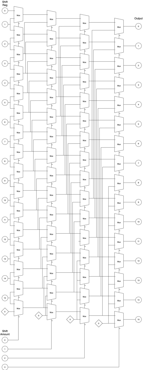
The image depicts a complex circuit diagram consisting of multiple components and connections. The diagram is organized into several sections, including the input, processing units, and output.
### Components/Axes
- **Input**: The input section is labeled "Shift Amount" and has a series of numbers ranging from 0 to 15.
- **Processing Units**: There are multiple processing units labeled "MUX" (Multiplexer), which are connected in a series.
- **Output**: The output section is labeled "Output" and has a series of numbers ranging from 0 to 15.
### Detailed Analysis or ### Content Details
The diagram shows a series of MUX units connected in a parallel configuration. Each MUX unit takes an input from the "Shift Amount" section and outputs a signal to the "Output" section. The input signals are processed through the MUX units, and the output signals are combined and sent to the "Output" section.
### Key Observations
- The diagram shows a total of 15 MUX units, each with a different input signal.
- The output signals are combined through a series of MUX units, and the final output signal is sent to the "Output" section.
- The diagram does not show any specific values or numerical data, but it does show a clear flow of signals through the circuit.
### Interpretation
The diagram demonstrates a complex circuit that takes an input signal, processes it through multiple MUX units, and produces an output signal. The circuit is designed to handle a large number of input signals and produce a single output signal. The diagram is a useful tool for understanding the flow of signals through a complex circuit and for designing and troubleshooting circuits.