## Digital Circuit Diagram: Multiplexer-Based Shift Register Array
### Overview
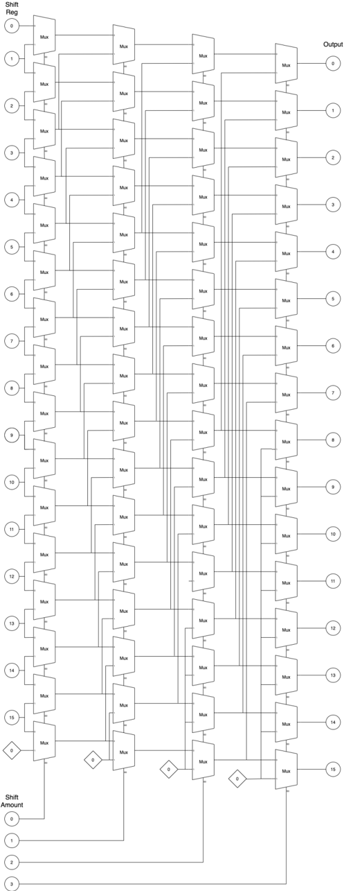
The diagram depicts a complex digital circuit composed of multiple multiplexers (Mux) arranged in a hierarchical structure. It includes a shift register (Shift Reg) on the left, a series of interconnected Mux blocks in the center, and an output section on the right. A "Shift Amount" control section is positioned at the bottom, suggesting variable data manipulation. The diagram uses standardized logic gate symbols and connectivity lines to represent signal flow.
### Components/Axes
- **Left Section (Shift Reg)**:
- Labeled "Shift Reg" with 16 input lines (0–15).
- Each input connects to a Mux block via vertical lines.
- **Central Section (Mux Array)**:
- 16 columns of Mux blocks, each labeled "Mux".
- Mux blocks are interconnected with horizontal and vertical lines, forming a grid-like structure.
- Some Mux blocks have additional control lines (e.g., "0" and "1" inputs at the bottom).
- **Right Section (Output)**:
- Labeled "Output" with 16 output lines (0–15).
- Each output line connects to a Mux block in the central section.
- **Bottom Section (Shift Amount)**:
- Labeled "Shift Amount" with 4 input lines (0–3).
- Lines from this section connect to the Mux blocks, likely controlling shift operations.
### Detailed Analysis
- **Shift Register (Shift Reg)**:
- 16 input lines (0–15) suggest a 16-bit register.
- Each input is routed to a corresponding Mux block, indicating parallel data processing.
- **Mux Blocks**:
- 16 columns of Mux blocks, each with multiple inputs and outputs.
- Horizontal and vertical connections imply a tree-like structure for data routing.
- Some Mux blocks have control inputs (e.g., "0" and "1" at the bottom), suggesting conditional selection.
- **Output Section**:
- 16 output lines (0–15) mirror the input structure, indicating a 16-bit output.
- Output lines are connected to the final Mux blocks, which may perform final data selection or transformation.
- **Shift Amount Control**:
- 4 input lines (0–3) likely represent a 2-bit control signal (since 2² = 4).
- These lines connect to the Mux blocks, enabling variable shift operations (e.g., shifting data by 0–3 positions).
### Key Observations
- **Hierarchical Mux Structure**: The Mux blocks form a layered network, suggesting a multi-stage data processing pipeline.
- **Symmetry in Input/Output**: The 16-input and 16-output lines indicate a balanced design for data flow.
- **Control Signals**: The "Shift Amount" section introduces variability, allowing dynamic data manipulation.
- **No Numerical Data**: The diagram lacks explicit numerical values beyond labels (e.g., 0–15, 0–3), focusing on structural relationships.
### Interpretation
This diagram represents a **multiplexer-based shift register array**, likely used for advanced data manipulation in digital systems. The hierarchical Mux structure enables parallel processing, while the "Shift Amount" control allows variable bit shifting. The 16-bit input/output suggests applications in high-speed data routing, such as in microprocessors or signal processing units. The absence of numerical data implies the diagram focuses on architectural design rather than performance metrics. The interconnected Mux blocks may optimize data flow efficiency, reducing latency in complex operations. The "Shift Amount" control highlights the system's adaptability, making it suitable for tasks requiring dynamic bit manipulation.