## Diagram: 4-bit Binary Multiplication Array
### Overview
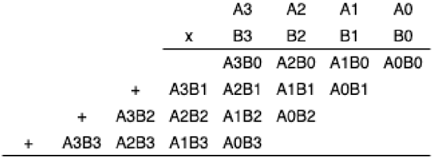
The image displays a symbolic representation of the multiplication process for two 4-bit binary numbers, using the standard "shift-and-add" algorithm. It shows the generation of partial products and their arrangement for summation. The diagram is purely structural, using symbolic terms (e.g., A3B0) rather than specific binary digits (0 or 1).
### Components/Axes
* **Operands (Top Row):**
* **Multiplicand:** Represented by bits `A3`, `A2`, `A1`, `A0` (from most significant bit, MSB, to least significant bit, LSB).
* **Multiplier:** Represented by bits `B3`, `B2`, `B1`, `B0` (from MSB to LSB).
* A multiplication symbol `x` is placed to the left of the multiplier row.
* A horizontal line separates the operands from the partial products.
* **Partial Products (Middle Rows):** Four rows of terms, each representing the product of one multiplier bit with all multiplicand bits. Each row is shifted left relative to the one above it.
* **Addition Symbols (`+`):** Placed at the beginning of the second, third, and fourth partial product rows, indicating these rows are to be added together.
* **Final Summation Line:** A horizontal line at the bottom, below which the final product would be written (though the product itself is not shown in this diagram).
### Detailed Analysis
The diagram breaks down the multiplication `A3A2A1A0 x B3B2B1B0` into its constituent partial products:
1. **First Partial Product Row (No shift):** `A3B0 A2B0 A1B0 A0B0`
* This is the result of multiplying the entire multiplicand (`A3A2A1A0`) by the LSB of the multiplier (`B0`).
2. **Second Partial Product Row (Shifted left by 1):** `+ A3B1 A2B1 A1B1 A0B1`
* This is the result of multiplying the multiplicand by the second multiplier bit (`B1`). The row is shifted one position to the left, which is equivalent to multiplying by 2 (in decimal).
3. **Third Partial Product Row (Shifted left by 2):** `+ A3B2 A2B2 A1B2 A0B2`
* Result of multiplying by `B2`. Shifted left by two positions (equivalent to multiplying by 4).
4. **Fourth Partial Product Row (Shifted left by 3):** `+ A3B3 A2B3 A1B3 A0B3`
* Result of multiplying by the MSB of the multiplier (`B3`). Shifted left by three positions (equivalent to multiplying by 8).
**Spatial Grounding:** The partial products form a descending staircase pattern from top-right to bottom-left. The `+` signs are vertically aligned on the far left, starting from the second row. The terms within each row are horizontally aligned with the terms in the row above, but offset one column to the left for each subsequent row.
### Key Observations
* **Symbolic Nature:** The diagram uses abstract labels (`A3B0`, etc.) to represent the logical AND operation between two bits. It does not contain actual binary values or numerical results.
* **Structural Completeness:** It correctly illustrates the generation of all 16 possible single-bit partial products (4 bits from A x 4 bits from B) for a 4x4 multiplication.
* **Implicit Addition:** The layout implies that all these partial products, with their respective shifts, must be summed to produce the final 8-bit product. The final sum is not computed or shown.
* **No Data or Trends:** This is a process diagram, not a data chart. It contains no numerical data points, trends, or outliers to analyze.
### Interpretation
This diagram is a fundamental teaching and reference tool in digital logic design and computer architecture. It visually explains the core algorithm that hardware multipliers implement.
* **What it demonstrates:** It breaks down the complex operation of multiplication into a series of simpler operations: generating partial products (via logical AND gates) and then adding them with appropriate weighting (via shifters and adders).
* **Relationship between elements:** The spatial shifting of each row directly corresponds to the binary weight of the multiplier bit (`B0`=1, `B1`=2, `B2`=4, `B3`=8). The `+` symbols explicitly mark the transition from product generation to the summation phase.
* **Underlying Principle:** The diagram embodies the Peircean concept of a **diagrammatic reasoning** icon. It is an iconic representation where the spatial relations between the symbols (the shifted rows) directly mirror the logical and mathematical relations in the multiplication process. By manipulating this diagram (i.e., performing the addition it implies), one can deduce the result of the multiplication. It serves as a static blueprint for a dynamic computational process.