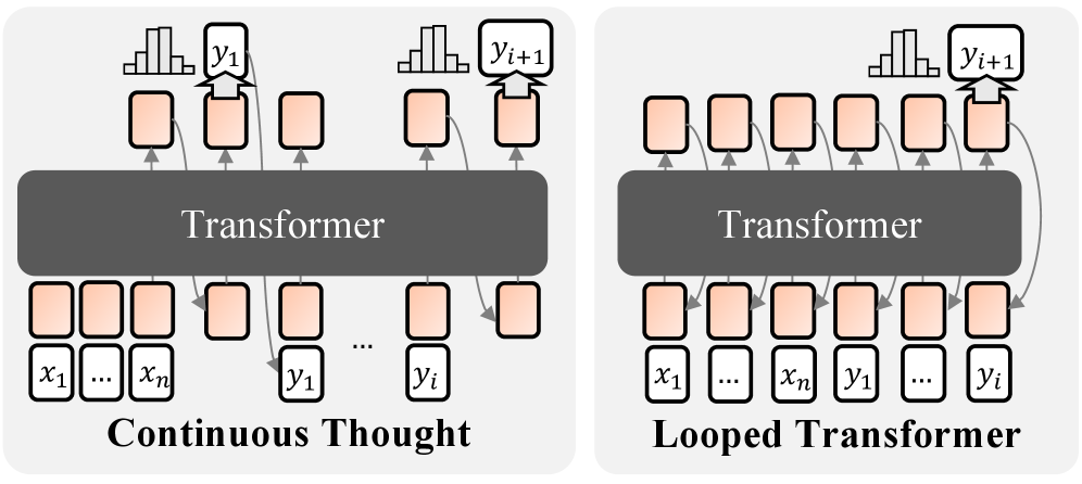
## Diagram: Continuous Thought vs. Looped Transformer Architectures
### Overview
The image presents two diagrams illustrating different transformer architectures: "Continuous Thought" and "Looped Transformer." Both diagrams depict a transformer model with input and output layers, but they differ in how the output is fed back into the model. The "Continuous Thought" model processes input sequentially, while the "Looped Transformer" model incorporates feedback loops from the output to the input.
### Components/Axes
* **Diagram Type:** Architectural diagrams
* **Elements:**
* **Transformer:** A central gray rounded rectangle labeled "Transformer" in both diagrams.
* **Input Layer (Continuous Thought):** A series of white rectangles labeled "x1", "...", "xn".
* **Output Layer (Continuous Thought):** A series of white rectangles labeled "y1", ..., "yi".
* **Input Layer (Looped Transformer):** A series of white rectangles labeled "x1", ..., "xn", "y1", ..., "yi".
* **Output Layer (Looped Transformer):** A series of white rectangles.
* **Intermediate Layers:** Orange-shaded rectangles connecting the input and output layers to the transformer.
* **Output Distribution:** Histograms above the output layer, labeled "yi+1".
* **Arrows:** Gray arrows indicating the flow of information.
### Detailed Analysis
**1. Continuous Thought:**
* **Input:** The input layer consists of a sequence of inputs denoted as x1 to xn. These are represented as white rectangles.
* **Processing:** The inputs are fed into the Transformer via orange-shaded intermediate layers.
* **Output:** The Transformer produces a sequence of outputs denoted as y1 to yi. These are represented as white rectangles.
* **Output Distribution:** Above the output layer, a histogram represents the distribution of the next predicted output, yi+1.
* **Flow:** The flow is sequential, from input to output, without any feedback loops.
**2. Looped Transformer:**
* **Input:** The input layer consists of a sequence of inputs denoted as x1 to xn, followed by y1 to yi. These are represented as white rectangles.
* **Processing:** The inputs are fed into the Transformer via orange-shaded intermediate layers.
* **Output:** The Transformer produces a sequence of outputs.
* **Output Distribution:** Above the output layer, a histogram represents the distribution of the next predicted output, yi+1.
* **Flow:** The flow includes feedback loops, where the output is fed back into the input layer. This is indicated by the gray arrows looping from the output layer back to the input layer.
### Key Observations
* The primary difference between the two architectures is the presence of feedback loops in the "Looped Transformer" model.
* The "Continuous Thought" model processes input sequentially without any feedback.
* Both models use a Transformer as the core processing unit.
* The input layer of the "Looped Transformer" includes both the initial input (x1 to xn) and the previous outputs (y1 to yi).
### Interpretation
The diagrams illustrate two different approaches to using transformer models. The "Continuous Thought" model is a standard sequential processing architecture, suitable for tasks where the output at one step does not depend on previous outputs. The "Looped Transformer" model, on the other hand, incorporates feedback loops, allowing the model to consider its previous outputs when generating new outputs. This architecture is suitable for tasks where the output is dependent on the history of previous outputs, such as language modeling or sequence generation. The "Looped Transformer" architecture enables the model to maintain a "memory" of previous states, which can be beneficial for tasks requiring long-term dependencies.