## Diagram: Neural Network Architecture with Channel and Time Mixing
### Overview
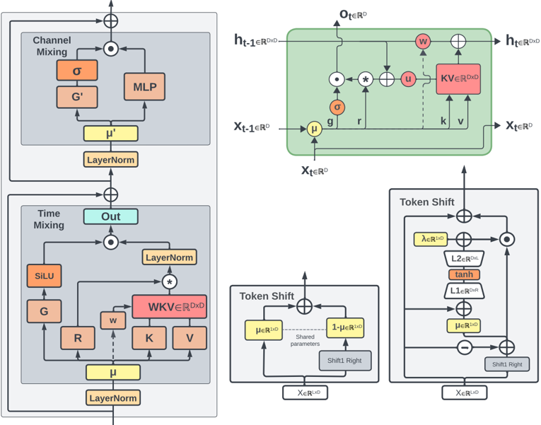
The image depicts a technical diagram of a neural network architecture, likely for a transformer-based model. It includes components for **Channel Mixing**, **Time Mixing**, **Token Shift**, and **KV (Key-Value) operations**. The diagram uses colored blocks, arrows, and mathematical notations to represent data flow and operations.
### Components/Axes
#### Left Side: Channel Mixing
- **Blocks**:
- **σ (sigma)**: Orange block, likely a sigmoid activation function.
- **G'**: Orange block, possibly a gate or transformation matrix.
- **MLP**: Orange block, representing a multi-layer perceptron.
- **μ'**: Yellow block, likely a mean or bias term.
- **LayerNorm**: Yellow block, layer normalization.
- **Flow**:
- Inputs: `σ` and `G'` feed into `MLP`, which outputs `μ'`.
- `μ'` is normalized via `LayerNorm`.
#### Right Side: Time Mixing
- **Blocks**:
- **Out**: Light blue block, output of the time mixing process.
- **SiLU**: Orange block, sigmoid linear unit activation.
- **G, R, w, WKV, K, V**: Orange blocks, representing gates, residual connections, weights, and key-value matrices.
- **LayerNorm**: Yellow block, normalization.
- **Flow**:
- Inputs: `G`, `R`, `w`, `K`, `V` are combined via `WKV` (Key-Value) operations.
- Output: `Out` after `LayerNorm`.
#### Token Shift Diagrams (Right Side)
1. **KV Block**:
- **Elements**:
- `h_{t-1} ∈ ℝ^{DxD}`: Hidden state from previous time step.
- `x_{t-1} ∈ ℝ^D`: Input at previous time step.
- `KV ∈ ℝ^{DxD}`: Key-Value matrix.
- `u, k, v`: Intermediate variables.
- **Flow**:
- `h_{t-1}` and `x_{t-1}` are combined via `KV` to produce `h_t`.
2. **Token Shift (Left)**:
- **Elements**:
- `λ ∈ ℝ^{1xD}`: Scaling parameter.
- `L2 ∈ ℝ^{DxL}`: Linear transformation.
- `tanh`: Hyperbolic tangent activation.
- `Shift1 Right`: Positional shift operation.
- **Flow**:
- `x_{t-1}` is transformed via `L2`, `tanh`, and `Shift1 Right`.
3. **Token Shift (Right)**:
- **Elements**:
- `μ ∈ ℝ^{1xD}`: Mean parameter.
- `1-μ ∈ ℝ^{1xD}`: Complementary parameter.
- `L1 ∈ ℝ^{DxR}`: Linear transformation.
- `Shift1 Right`: Positional shift.
- **Flow**:
- `x_{t-1}` is split into `μ` and `1-μ`, then transformed via `L1` and `Shift1 Right`.
### Detailed Analysis
- **Channel Mixing**:
- Combines `σ` and `G'` via `MLP` to generate `μ'`, which is normalized.
- Uses `LayerNorm` to stabilize training.
- **Time Mixing**:
- Integrates `G`, `R`, `w`, `K`, and `V` through `WKV` operations.
- Outputs `Out` after normalization.
- **Token Shift**:
- Involves positional encoding via `Shift1 Right` and parameterized transformations (`λ`, `L1`, `L2`).
- Uses `tanh` for non-linearity and `LayerNorm` for stability.
### Key Observations
- **Color Coding**:
- Orange blocks represent activation functions (`σ`, `SiLU`, `tanh`).
- Yellow blocks denote normalization (`LayerNorm`, `μ`, `μ'`).
- Red blocks (`WKV`) indicate key-value operations.
- **Mathematical Notations**:
- `ℝ^D`, `ℝ^{DxD}`: Dimensionality of input/output spaces.
- `Shift1 Right`: Likely a cyclic shift operation for positional encoding.
### Interpretation
This diagram illustrates a hybrid neural network architecture combining **channel-wise** and **time-wise** mixing mechanisms, common in transformer variants like **Mamba** or **SSM (State Space Models)**.
- **Channel Mixing** focuses on feature interactions within a single time step.
- **Time Mixing** captures temporal dependencies across steps.
- **Token Shift** introduces positional encoding via parameterized shifts, replacing traditional positional embeddings.
- The use of `LayerNorm` and `MLP` suggests a focus on stability and non-linear transformations.
The architecture likely optimizes for efficiency in sequence modeling tasks, balancing computational complexity with performance. The `WKV` block and `Token Shift` operations highlight innovations in attention mechanisms and positional encoding.