## System Diagram: Mono Audio Codec and Binaural Decoder
### Overview
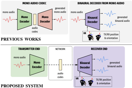
The image presents two system diagrams: one illustrating a "Previous Works" approach to mono audio codec, and the other depicting a "Proposed System" involving a transmitter end, network, and receiver end for binaural audio decoding from mono audio.
### Components/Axes
**Previous Works (Top)**
* **Title:** MONO AUDIO CODEC (left), BINAURAL DECODER FROM MONO AUDIO (right)
* **Left Diagram:**
* **Input:** "mono audio" (red waveform)
* **Component 1:** "Mono Encoder" (green trapezoid)
* **Intermediate:** "audio codes" (yellow rectangle)
* **Component 2:** "Mono Decoder" (red trapezoid)
* **Output:** "generated mono audio" (red waveform)
* **Right Diagram:**
* **Input:** "mono audio" (red waveform)
* **Component:** "Binaural Decoder" (purple trapezoid)
* **Output:** "generated binaural audio" (two blue waveforms)
* **Additional Inputs:** "VR" (Virtual Reality headset icon), "TX/RX position & orientation" (text near VR icon)
**Proposed System (Bottom)**
* **Title:** PROPOSED SYSTEM
* **Left Section (TRANSMITTER END):**
* **Input:** "mono audio" (red waveform)
* **Component:** "Mono Encoder" (green trapezoid)
* **Middle Section (NETWORK):**
* **Component:** "audio codes" (yellow rectangle, dashed lines connecting to adjacent sections)
* **Right Section (RECEIVER END):**
* **Component:** "Binaural Decoder" (purple trapezoid)
* **Output:** "generated binaural audio" (two blue waveforms)
* **Additional Inputs:** "VR" (Virtual Reality headset icon), "TX/RX position & orientation" (text near VR icon)
### Detailed Analysis
**Previous Works - Mono Audio Codec:**
1. **Input Audio:** A red waveform labeled "mono audio" enters the "Mono Encoder."
2. **Mono Encoder:** The green "Mono Encoder" processes the audio.
3. **Audio Codes:** The encoded audio is represented as a yellow rectangle labeled "audio codes."
4. **Mono Decoder:** The "Mono Decoder" (red) receives the audio codes.
5. **Output Audio:** A red waveform labeled "generated mono audio" exits the "Mono Decoder."
**Previous Works - Binaural Decoder from Mono Audio:**
1. **Input Audio:** A red waveform labeled "mono audio" enters the "Binaural Decoder."
2. **Binaural Decoder:** The purple "Binaural Decoder" processes the audio.
3. **Output Audio:** Two blue waveforms labeled "generated binaural audio" exit the "Binaural Decoder."
4. **VR Input:** A VR headset icon and the text "TX/RX position & orientation" indicate that the decoder uses VR-related data.
**Proposed System:**
1. **Transmitter End:**
* A red waveform labeled "mono audio" enters the "Mono Encoder" (green).
2. **Network:**
* The encoded audio is represented as a yellow rectangle labeled "audio codes." Dashed lines connect this to the "Mono Encoder" and "Binaural Decoder."
3. **Receiver End:**
* The "Binaural Decoder" (purple) receives the audio codes.
* Two blue waveforms labeled "generated binaural audio" exit the "Binaural Decoder."
* A VR headset icon and the text "TX/RX position & orientation" indicate that the decoder uses VR-related data.
### Key Observations
* The "Previous Works" section shows two separate systems: a mono audio codec and a binaural decoder.
* The "Proposed System" integrates the mono audio encoding and binaural decoding into a single system with a network component.
* Both binaural decoding systems utilize VR-related data ("VR" and "TX/RX position & orientation").
* The "Proposed System" separates the encoding and decoding processes into "Transmitter End" and "Receiver End" sections, connected by a "Network."
### Interpretation
The diagrams illustrate the evolution from separate mono audio processing and binaural decoding systems to a unified system designed for network transmission and VR integration. The "Proposed System" suggests a more complex and potentially more efficient approach to generating binaural audio from mono audio, particularly in VR applications. The separation of transmitter and receiver ends implies a system designed for remote or distributed audio processing.