## Diagram & Chart Compilation: Neural Network Architecture, Chip Implementation, and Accuracy Comparison
### Overview
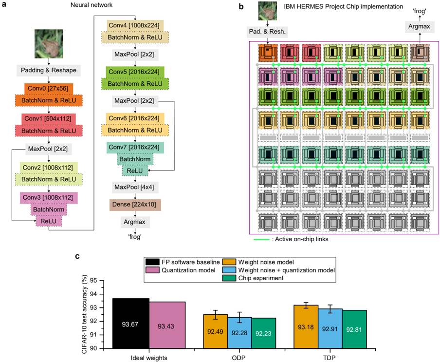
The image presents a compilation of three distinct but related elements: (a) a diagram illustrating the architecture of a neural network, (b) a visual representation of the IBM HERMES Project Chip implementation, and (c) a bar chart comparing the CIFAR-10 test accuracy of different models and implementations. The overall theme appears to be the implementation of a neural network on specialized hardware and the evaluation of its performance.
### Components/Axes
**(a) Neural Network Diagram:**
* **Components:** Padding & Reshape, Conv0, Conv1, Conv2, Conv3, Conv4, Conv5, Conv6, Conv7, Dense, Argmax.
* **Layers & Dimensions:** Conv0 [27x56], Conv1 [504x112], Conv2 [1008x112], Conv3 [1008x112], Conv4 [1008x224], Conv5 [2016x224], Conv6 [2016x224], Conv7 [2016x224], Dense [224x10].
* **Operations:** BatchNorm & ReLU, MaxPool [2x2], MaxPool [4x4].
**(b) IBM HERMES Chip Implementation:**
* **Labels:** "Pad. & Resh.", "Argmax", "frog", "Active on-chip links".
* **Visual Representation:** A grid of colored squares representing the chip's structure, with connections indicated by lines.
**(c) CIFAR-10 Test Accuracy Chart:**
* **X-axis:** "Ideal weights", "ODP", "TDP".
* **Y-axis:** "CIFAR-10 test accuracy (%)", ranging from 90 to 95.
* **Legend:**
* FP software baseline (Dark Red)
* Quantization model (Purple)
* Weight noise model (Blue)
* Weight noise + quantization model (Green)
* Chip experiment (Orange)
### Detailed Analysis or Content Details
**(a) Neural Network Diagram:**
The diagram shows a sequential flow of operations. The network begins with a Padding & Reshape layer, followed by a series of convolutional layers (Conv0 to Conv7) interspersed with Batch Normalization & ReLU activation functions and Max Pooling layers. The final layers consist of a Dense layer and an Argmax layer, which outputs "frog". The dimensions of each convolutional layer are explicitly stated.
**(b) IBM HERMES Chip Implementation:**
This section visually depicts the chip's architecture. The colored squares likely represent different processing units or memory blocks. The lines connecting these squares indicate data flow or communication pathways. The labels "Pad. & Resh." and "Argmax" suggest that these specific neural network operations are implemented within the chip. The image of a "frog" is present, likely related to the network's classification task.
**(c) CIFAR-10 Test Accuracy Chart:**
* **FP software baseline:** Approximately 93.67% accuracy across all three conditions (Ideal weights, ODP, TDP).
* **Quantization model:** Approximately 93.43% accuracy across all three conditions.
* **Weight noise model:**
* Ideal weights: ~92.49%
* ODP: ~92.28%
* TDP: ~92.23%
* **Weight noise + quantization model:**
* Ideal weights: ~93.18%
* ODP: ~92.91%
* TDP: ~92.81%
* **Chip experiment:**
* Ideal weights: ~93.18%
* ODP: ~92.91%
* TDP: ~92.81%
The error bars are present for the Weight noise model, Weight noise + quantization model, and Chip experiment.
### Key Observations
* The FP software baseline consistently achieves the highest accuracy.
* The quantization model shows a slight decrease in accuracy compared to the baseline.
* Introducing weight noise further reduces accuracy, especially in the ODP and TDP conditions.
* Combining weight noise and quantization results in accuracy levels similar to the weight noise model alone.
* The chip experiment performs similarly to the weight noise + quantization model.
* Accuracy tends to decrease slightly when moving from Ideal weights to ODP and TDP conditions for the models incorporating noise.
### Interpretation
The data suggests that while the IBM HERMES chip can successfully implement the neural network, it introduces some performance degradation compared to a purely software-based implementation. The accuracy loss is likely due to the quantization and the introduction of noise during the chip's operation. The consistent performance of the chip experiment with the weight noise + quantization model indicates that the chip's limitations are closely tied to the effects of quantization and noise.
The decreasing accuracy from Ideal weights to ODP and TDP suggests that these conditions represent increasing levels of hardware constraints or imperfections. ODP and TDP likely refer to different operating conditions or power/performance trade-offs within the chip.
The presence of the "frog" label in both the neural network diagram and the chip implementation suggests that the network is designed for image classification, specifically identifying frogs. The overall study appears to be an evaluation of the trade-offs between accuracy, efficiency, and hardware constraints in deploying a neural network on a specialized chip. The data highlights the challenges of maintaining accuracy when moving from a software baseline to a hardware implementation, particularly when dealing with quantization and noise.