## Diagram: Neuromorphic Computing Architecture and Memristor Operation
### Overview
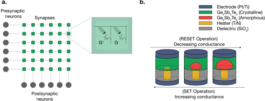
The image presents a schematic of a neuromorphic computing architecture using memristors as synaptic elements. Part (a) illustrates the network structure with presynaptic and postsynaptic neurons connected by a grid of synapses. Part (b) depicts the operational principle of a memristor, showing the transition between crystalline and amorphous states to modulate conductance during RESET and SET operations.
### Components/Axes
**Part a:**
* **Nodes:** Represented by circles (neurons) and squares (synapses).
* **Presynaptic neurons:** Located on the left side of the diagram.
* **Synapses:** Arranged in a grid pattern connecting presynaptic and postsynaptic neurons.
* **Postsynaptic neurons:** Located at the bottom of the diagram.
* **Connections:** Lines connecting neurons and synapses.
* **Inset:** A magnified view of a synapse, showing two memristor circuits labeled G+ and G-.
**Part b:**
* **Legend (Top-Right):**
* **Blue:** Electrode (Pt/Ti)
* **Green:** Ge₂Sb₂Te₅ (Crystalline)
* **Red:** Ge₂Sb₂Te₅ (Amorphous)
* **Yellow:** Heater (TiN)
* **Gray:** Dielectric (SiO₂)
* **Memristor Operation Diagrams:** Three cylindrical diagrams illustrating the memristor's state during RESET and SET operations.
* **RESET Operation:** Labeled above the diagrams, indicating decreasing conductance.
* **SET Operation:** Labeled below the diagrams, indicating increasing conductance.
* **Arrow:** A double-headed arrow below the diagrams indicates the direction of the SET operation (increasing conductance), while an arrow above the diagrams indicates the direction of the RESET operation (decreasing conductance).
### Detailed Analysis
**Part a: Neuromorphic Network**
* The network consists of 6 presynaptic neurons and 6 postsynaptic neurons.
* The synapses form a 6x6 grid, with each synapse connecting a presynaptic neuron to a postsynaptic neuron.
* The inset shows a simplified circuit diagram of a synapse, containing two memristors (G+ and G-) connected in a specific configuration.
**Part b: Memristor Operation**
* The memristor consists of several layers: Electrode (Pt/Ti), Ge₂Sb₂Te₅ (Crystalline/Amorphous), Heater (TiN), and Dielectric (SiO₂).
* **Initial State:** The first diagram shows the heater (yellow) surrounded by the dielectric (gray), with the crystalline Ge₂Sb₂Te₅ (green) above, and the electrode (blue) on top.
* **RESET Operation (Decreasing Conductance):** As the memristor undergoes RESET operation, the heater causes a portion of the crystalline Ge₂Sb₂Te₅ to transform into the amorphous state (red). The amorphous region grows in size from left to right in the diagrams.
* **SET Operation (Increasing Conductance):** The reverse process, where the amorphous region transforms back into the crystalline state, increases the conductance.
### Key Observations
* The neuromorphic network architecture utilizes memristors as synaptic elements.
* The conductance of the memristor is modulated by changing the phase of the Ge₂Sb₂Te₅ material between crystalline and amorphous states.
* RESET operation decreases conductance by increasing the amorphous region, while SET operation increases conductance by increasing the crystalline region.
### Interpretation
The image illustrates a fundamental concept in neuromorphic computing, where memristors are used to mimic the behavior of biological synapses. The ability to modulate the conductance of memristors allows for the implementation of artificial neural networks that can learn and adapt like the human brain. The RESET and SET operations demonstrate how the memristor's resistance can be dynamically adjusted, enabling the storage and processing of information within the network. The use of Ge₂Sb₂Te₅, a phase-change material, is crucial for achieving this dynamic resistance modulation. The architecture and operational principles shown in the image are essential for developing energy-efficient and high-performance neuromorphic computing systems.