## Diagram: Neuromorphic Synapse Array with Conductance Modulation Device
### Overview
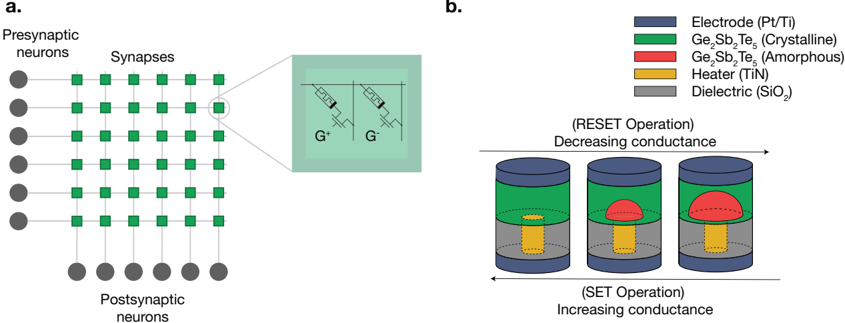
The image presents two interconnected technical diagrams:
1. **Left Panel (a)**: A schematic of a neuromorphic neural network with presynaptic and postsynaptic neurons connected via synapses.
2. **Right Panel (b)**: A legend defining material components and a cylindrical diagram illustrating conductance modulation (RESET/SET operations) in a memory device.
---
### Components/Axes
#### Panel a: Neural Network
- **Labels**:
- **Presynaptic neurons**: Gray circles on the left.
- **Synapses**: Green squares connecting presynaptic and postsynaptic neurons.
- **Postsynaptic neurons**: Gray circles on the right.
- **Inset**:
- **G⁺/G⁻**: Symbols representing excitatory (G⁺) and inhibitory (G⁻) synaptic states.
- **Legend (Panel b)**:
- **Electrode (Pt/Ti)**: Blue.
- **Ge₂Sb₂Te₅ (Crystalline)**: Green.
- **Ge₂Sb₂Te₅ (Amorphous)**: Red.
- **Heater (TiN)**: Yellow.
- **Dielectric (SiO₂)**: Gray.
#### Panel b: Conductance Modulation Device
- **Cylindrical Diagram**:
- **Layers**:
1. **Electrode (Pt/Ti)**: Blue outer layer.
2. **Ge₂Sb₂Te₅ (Crystalline)**: Green middle layer.
3. **Heater (TiN)**: Yellow inner layer.
4. **Dielectric (SiO₂)**: Gray base.
- **Arrows**:
- **RESET Operation**: Left-to-right arrow labeled "Decreasing conductance."
- **SET Operation**: Right-to-left arrow labeled "Increasing conductance."
---
### Detailed Analysis
#### Panel a: Neural Network
- **Structure**:
- 5 presynaptic neurons connect to 5 postsynaptic neurons via 25 synapses (5×5 grid).
- Synapses are uniformly green, suggesting identical initial conductance states.
- **Inset**:
- **G⁺/G⁻**: Indicates synaptic plasticity, with G⁺ (excitatory) and G⁻ (inhibitory) states.
#### Panel b: Conductance Modulation Device
- **RESET Operation**:
- Red amorphous Ge₂Sb₂Te₅ layer shrinks, reducing conductance.
- **SET Operation**:
- Red amorphous layer expands, increasing conductance.
- **Material Roles**:
- **Heater (TiN)**: Yellow layer generates heat to drive phase changes in Ge₂Sb₂Te₅.
- **Dielectric (SiO₂)**: Gray base insulates the structure.
---
### Key Observations
1. **Color Consistency**:
- Red in the legend (Ge₂Sb₂Te₅ amorphous) matches the red layer in the cylindrical diagram.
- Green (Ge₂Sb₂Te₅ crystalline) and yellow (TiN heater) align with their respective layers.
2. **Conductance Dynamics**:
- RESET reduces conductance by crystallizing Ge₂Sb₂Te₅ (thinner layer).
- SET increases conductance by amorphizing Ge₂Sb₂Te₅ (thicker layer).
3. **Neural Network Context**:
- Synapses likely model synaptic plasticity, with G⁺/G⁻ states mimicking biological synapses.
---
### Interpretation
This diagram illustrates a **neuromorphic computing system** where:
- **Synaptic Plasticity**: The neural network (Panel a) mimics biological synapses, with G⁺/G⁻ states representing excitatory/inhibitory signaling.
- **Resistive Memory**: The cylindrical device (Panel b) uses phase-change materials (Ge₂Sb₂Te₅) to modulate conductance via RESET/SET operations. The amorphous (red) and crystalline (green) phases of Ge₂Sb₂Te₅ directly control conductance, enabling memory storage.
- **Material Synergy**:
- The TiN heater (yellow) provides thermal energy to drive phase transitions in Ge₂Sb₂Te₅.
- Pt/Ti electrodes (blue) and SiO₂ dielectric (gray) form the electrical interface.
**Significance**: This system bridges biological neural networks and artificial memory devices, enabling energy-efficient, adaptive computing. The RESET/SET operations mirror synaptic strengthening/weakening, critical for machine learning applications.