\n
## Diagram: FHE Stack
### Overview
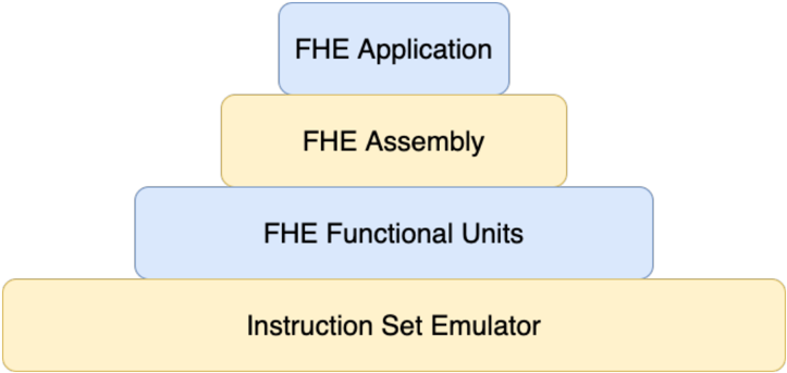
The image depicts a layered diagram representing a Fully Homomorphic Encryption (FHE) stack. It illustrates the different levels of abstraction involved in building an FHE application, from the underlying hardware emulation to the final application layer. The diagram is structured as a pyramid, with the base representing the lowest level and the apex representing the highest level.
### Components/Axes
The diagram consists of four rectangular blocks stacked vertically, each representing a different layer:
1. **Instruction Set Emulator:** Located at the bottom (base) of the pyramid.
2. **FHE Functional Units:** Situated above the Instruction Set Emulator.
3. **FHE Assembly:** Positioned above the FHE Functional Units.
4. **FHE Application:** Located at the top (apex) of the pyramid.
There are no axes or legends present in this diagram.
### Detailed Analysis or Content Details
The diagram shows a hierarchical relationship between the four layers. Each layer builds upon the one below it. The layers are visually distinguished by their color:
* **Instruction Set Emulator:** Light yellow.
* **FHE Functional Units:** Light blue.
* **FHE Assembly:** Light yellow.
* **FHE Application:** Light blue.
The text within each block is centered and clearly legible. The blocks are arranged in a pyramid shape, suggesting a dependency structure where higher layers rely on the functionality provided by lower layers.
### Key Observations
The diagram emphasizes the layered architecture of an FHE system. It highlights the progression from low-level hardware emulation to high-level application development. The alternating colors of the layers (yellow and blue) may be intended to visually separate different types of components or functionalities.
### Interpretation
This diagram illustrates the software stack required to implement FHE. The Instruction Set Emulator provides the foundational hardware abstraction. The FHE Functional Units build upon this to provide basic FHE operations. The FHE Assembly layer combines these operations into more complex routines. Finally, the FHE Application layer utilizes these routines to create a fully functional application that leverages the benefits of FHE.
The pyramid shape suggests that the complexity increases as you move up the stack. The lower layers are more fundamental and provide the building blocks for the higher layers. The diagram implies that developing FHE applications requires expertise in multiple areas, including hardware emulation, FHE primitives, and software engineering. The diagram does not provide any quantitative data or specific details about the implementation of each layer. It is a conceptual representation of the FHE stack.