## Diagram: FHE System Architecture Stack
### Overview
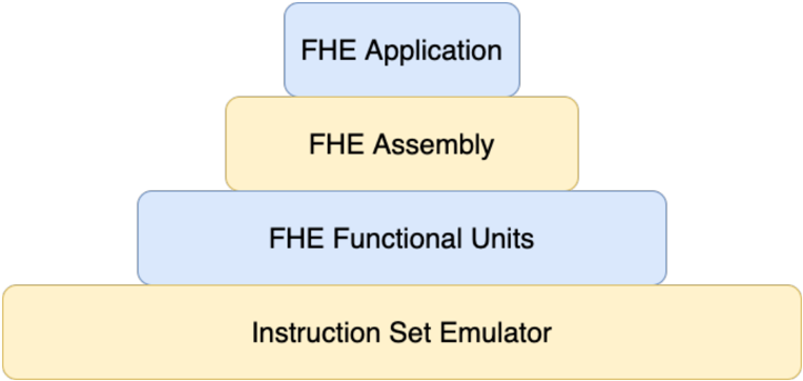
The image displays a four-layer hierarchical architecture diagram, presented as a stack of rounded rectangular boxes. The diagram illustrates the component layers of a system related to Fully Homomorphic Encryption (FHE). The layers are stacked vertically, with each box centered above the one below it, creating a pyramid-like structure that suggests a foundational relationship where lower layers support the ones above.
### Components/Axes
The diagram consists of four distinct layers, each represented by a colored box containing a text label. The layers are ordered from top (highest abstraction) to bottom (lowest level/foundation).
1. **Top Layer (Position: Top-center)**
* **Color:** Light blue
* **Label Text:** "FHE Application"
2. **Second Layer (Position: Center, directly below the top layer)**
* **Color:** Light yellow/beige
* **Label Text:** "FHE Assembly"
3. **Third Layer (Position: Center, directly below the second layer)**
* **Color:** Light blue
* **Label Text:** "FHE Functional Units"
4. **Bottom Layer (Position: Bottom-center, forming the base)**
* **Color:** Light yellow/beige
* **Label Text:** "Instruction Set Emulator"
### Detailed Analysis
The diagram is purely structural and contains no numerical data, charts, or complex data flows. Its information is conveyed through the labels and the spatial arrangement of the boxes.
* **Spatial Arrangement:** The boxes are stacked with consistent vertical spacing. The width of the boxes increases slightly from top to bottom, with the "Instruction Set Emulator" box being the widest, visually reinforcing its role as the foundational layer.
* **Color Pattern:** The layers alternate in color: Blue (Application) -> Yellow (Assembly) -> Blue (Functional Units) -> Yellow (Emulator). This pattern may be used to visually group or differentiate between layers of different types (e.g., software vs. hardware abstraction).
* **Text Transcription:** All text is in English and is transcribed exactly as it appears within each box.
### Key Observations
1. **Hierarchical Abstraction:** The diagram clearly depicts a layered software or system architecture. The progression from "Instruction Set Emulator" at the bottom to "FHE Application" at the top represents increasing levels of abstraction, moving from low-level hardware emulation to high-level user applications.
2. **Foundational Role:** The "Instruction Set Emulator" is the widest box and forms the base, indicating it is the core, foundational component upon which all other FHE-specific layers are built.
3. **FHE-Specific Layers:** The three upper layers are explicitly prefixed with "FHE," indicating they are specialized components for performing Fully Homomorphic Encryption operations. The "Instruction Set Emulator" is a more general computing component.
4. **Alternating Color Scheme:** The consistent blue-yellow-blue-yellow pattern from top to bottom suggests a potential categorical distinction between adjacent layers, though the specific meaning of the colors is not defined in the diagram itself.
### Interpretation
This diagram represents the **software stack for a Fully Homomorphic Encryption (FHE) system**. FHE is a form of encryption that allows computations to be performed directly on encrypted data without decrypting it first.
* **Layer Relationships:** The stack shows how an FHE application is ultimately executed. The high-level "FHE Application" likely defines encrypted computations. These are compiled or translated into "FHE Assembly," a lower-level code specific to the FHE operations. The "FHE Functional Units" layer represents the hardware or optimized software modules that perform the core cryptographic operations (like addition and multiplication on ciphertexts). Finally, the "Instruction Set Emulator" provides the base computational environment, potentially simulating a processor instruction set that the FHE functional units extend or utilize.
* **Architectural Insight:** The diagram emphasizes that FHE is not a single monolithic tool but a complex system built in layers. It highlights the need for specialized assembly languages and functional units to make FHE practical, sitting atop a more conventional computing foundation.
* **Notable Absence:** The diagram does not show data flow, control flow, or interfaces between the layers. It is a static, structural view of the component hierarchy. The primary information conveyed is the **existence and order of these four key architectural layers** in an FHE system.