## Diagram Type: Hierarchical Structure
### Overview
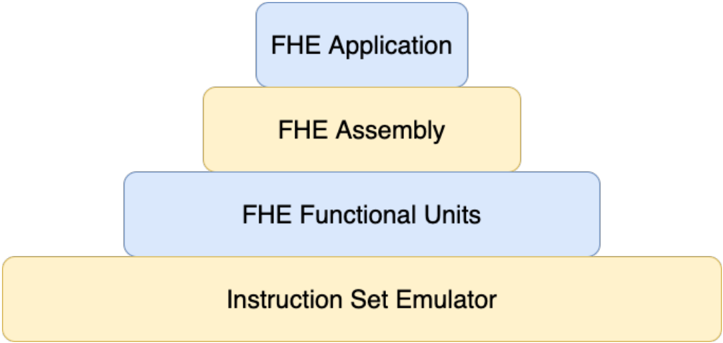
The image displays a hierarchical structure diagram that represents the components of an Instruction Set Emulator (ISE). The diagram is organized in a top-down manner, with each level indicating a different component of the ISE.
### Components/Axes
- **Instruction Set Emulator**: The bottom level of the diagram, representing the entire system.
- **FHE Functional Units**: The second level, indicating the functional units within the ISE.
- **FHE Assembly**: The third level, representing the assembly process within the ISE.
- **FHE Application**: The top level, indicating the application of the ISE.
### Detailed Analysis or ### Content Details
The diagram uses different colors to differentiate between the levels and components. The Instruction Set Emulator is represented by a large, light yellow rectangle. The FHE Functional Units are represented by a medium blue rectangle, the FHE Assembly by a light blue rectangle, and the FHE Application by a dark blue rectangle.
### Key Observations
- The diagram is well-organized, with each level clearly separated from the others.
- The colors used for each level are distinct, making it easy to distinguish between them.
- The diagram does not contain any numerical values or data points.
### Interpretation
The diagram provides a clear representation of the hierarchical structure of an Instruction Set Emulator. It shows how the ISE is composed of different functional units, which are then assembled to form the complete system. The application of the ISE is at the top level, indicating that it is the final output of the system. The diagram is useful for understanding the architecture of the ISE and how its components interact with each other.