## Memristor Array Diagram
### Overview
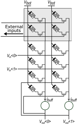
The image depicts a memristor crossbar array with input and output connections. It shows a 2x3 grid of memristor devices, with voltage inputs on the rows and current buffers on the columns. The diagram illustrates how external inputs are connected to the array, and how output voltages are derived from the current buffers.
### Components/Axes
* **Memristor Devices:** Represented by a symbol resembling a resistor with a curved line inside.
* **Input Voltages:** Labeled as V<sub>in</sub><0> and V<sub>in</sub><1>, indicating two input lines.
* **Output Voltages:** Labeled as V<sub>out</sub><0> and V<sub>out</sub><1>, indicating two output lines.
* **Bottom Voltages:** Labeled as V<sub>bot</sub> at the top of each column.
* **Current Buffers:** Represented by circles labeled as i<sub>buff</sub>.
* **External Inputs:** An arrow pointing into the array, labeled "External inputs".
* **Gray Shaded Region:** Highlights a portion of the array, specifically the top row.
### Detailed Analysis
The diagram shows a 2x2 array of memristors, with each memristor connected between a horizontal input line and a vertical output line.
* **Input Lines:** Two horizontal input lines are labeled V<sub>in</sub><0> and V<sub>in</sub><1>.
* **Output Lines:** Two vertical output lines connect to current buffers (i<sub>buff</sub>), which then connect to the output voltages V<sub>out</sub><0> and V<sub>out</sub><1>.
* **Top Row:** The top row of memristors is connected to V<sub>bot</sub>.
* **External Inputs:** The "External inputs" arrow indicates that the array receives external signals.
* **Memristor Connections:** Each memristor has one terminal connected to a horizontal input line and the other terminal connected to a vertical output line.
### Key Observations
* The diagram illustrates a basic memristor crossbar architecture.
* The input voltages control the state of the memristors.
* The current buffers provide stable output voltages.
* The gray shaded region highlights a specific section of the array, possibly indicating a particular operation or configuration.
### Interpretation
The diagram represents a fundamental building block for memristor-based memory or computation. The memristor array allows for storing and processing information based on the resistance states of the individual memristors. The input voltages determine the state of the memristors, and the output voltages reflect the stored information or the result of a computation. The "External inputs" suggest that the array can be integrated into a larger system. The use of current buffers ensures that the output voltages are stable and can be reliably read.