## Data Flow Diagram: Processor Communication Over Time
### Overview
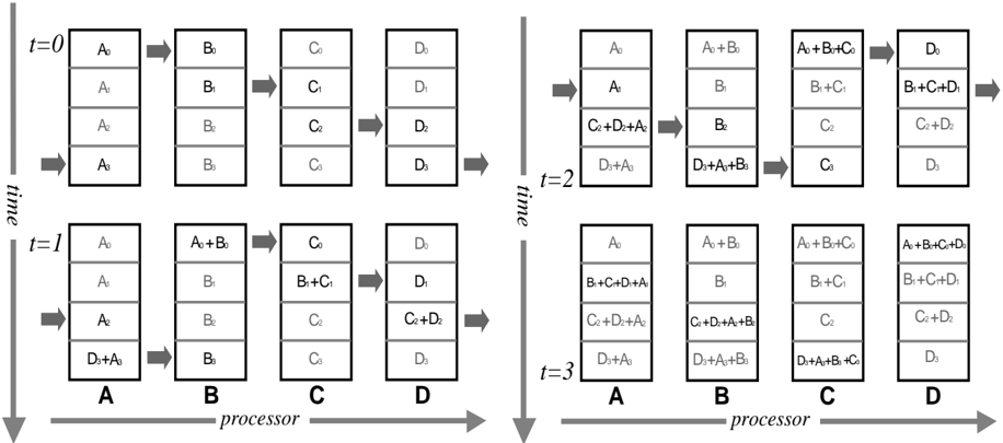
The diagram illustrates the flow of data elements (A0-A3, B0-B3, C0-C3, D0-D3) across four processors (A, B, C, D) over four discrete time steps (t=0 to t=3). Arrows indicate data movement and combination between processors, with each processor accumulating and merging data elements sequentially.
### Components/Axes
- **Processors**: Labeled A, B, C, D (horizontal axis, left to right).
- **Time Steps**: Labeled t=0, t=1, t=2, t=3 (vertical axis, top to bottom).
- **Data Elements**:
- Processor A: A0, A1, A2, A3
- Processor B: B0, B1, B2, B3
- Processor C: C0, C1, C2, C3
- Processor D: D0, D1, D2, D3
- **Arrows**: Represent data transfer and combination (e.g., "A0+B0" indicates merged data from A and B).
### Detailed Analysis
#### Time Step t=0
- **Processor A**: A0, A1, A2, A3
- **Processor B**: B0, B1, B2, B3
- **Processor C**: C0, C1, C2, C3
- **Processor D**: D0, D1, D2, D3
- **Flow**: No data transfer; initial state.
#### Time Step t=1
- **Processor A**: A0, A1, A2, D3+A3 (A3 merged with D3)
- **Processor B**: A0+B0, B1, B2, B3
- **Processor C**: B1+C1, C2, C3
- **Processor D**: C2+D2, D3
- **Flow**:
- A → B: A0+B0
- B → C: B1+C1
- C → D: C2+D2
- D → A: D3+A3
#### Time Step t=2
- **Processor A**: A0, B1, C2+D2+A2, D3+A3
- **Processor B**: A0+B0, B1, C2, D3+A3+B3
- **Processor C**: A0+B0+C0, B1+C1, C2, D3+A3+B3+C3
- **Processor D**: B1+C1+D1, C2+D2, D3
- **Flow**:
- A → B: A0+B0
- B → C: B1+C1
- C → D: C2+D2
- D → A: D3+A3
#### Time Step t=3
- **Processor A**: A0+B0+C0, B1+C1+D1+A1, C2+D2+A2, D3+A3
- **Processor B**: A0+B0+C0+D0, B1+C1+D1, C2+D2, D3+A3+B3
- **Processor C**: A0+B0+C0+D0, B1+C1+D1+A1, C2+D2+A2, D3+A3+B3+C3
- **Processor D**: B1+C1+D1+A1, C2+D2+A2+B2, D3+A3+B3+C3
- **Flow**:
- A → B: A0+B0+C0
- B → C: B1+C1+D1
- C → D: C2+D2+A2
- D → A: D3+A3+B3
### Key Observations
1. **Incremental Aggregation**: Each processor accumulates data from prior steps, merging elements from upstream processors (e.g., D3+A3 at t=1).
2. **Full System Integration**: By t=3, all processors contain combined data from all initial elements (e.g., Processor D holds B1+C1+D1+A1).
3. **Symmetric Flow**: Data moves unidirectionally (A→B→C→D→A) with periodic wrapping at t=3.
### Interpretation
The diagram models a **parallel computing workflow** where processors iteratively aggregate data across a ring topology. Each time step represents a synchronization phase, with processors combining their local data with incoming elements. The final state (t=3) shows complete data fusion, suggesting applications in distributed systems, fault tolerance, or parallel algorithms requiring global data synchronization. The structured flow ensures no data loss, with each element propagated systematically through the network.