\n
## Diagram: Kernel Transformation
### Overview
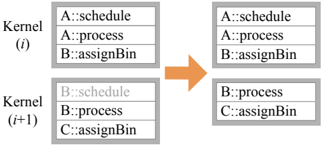
The image depicts a transformation between two sets of kernels, labeled "(i)" and "(i+1)". Each kernel is represented as a rectangular box containing three lines of text, formatted as "Letter::Operation". An orange arrow indicates the direction of the transformation from the left side to the right side.
### Components/Axes
The diagram consists of two main sections:
* **Kernel (i):** The initial state of the kernels.
* **Kernel (i+1):** The transformed state of the kernels.
Each kernel contains three entries, each with a letter and an operation.
### Detailed Analysis or Content Details
**Kernel (i):**
* Row 1: A::schedule
* Row 2: A::process
* Row 3: B::assignBin
**Kernel (i+1):**
* Row 1: A::schedule
* Row 2: A::process
* Row 3: B::assignBin
**Transformation:**
The transformation appears to involve a shift in the letter associated with the operations. Specifically:
* The first kernel (i) has operations associated with letters A and B.
* The second kernel (i+1) has operations associated with letters A, B, and C.
* The first two rows remain unchanged (A::schedule and A::process).
* The third row changes from B::assignBin to C::assignBin.
* The bottom kernel (i) has operations associated with letters B and C.
* The bottom kernel (i+1) has operations associated with letters B and C.
* The second row remains unchanged (B::process).
* The third row changes from C::assignBin to C::assignBin.
### Key Observations
The transformation appears to be a sequential update of the kernels, where the letter associated with the "assignBin" operation increments from B to C. The other operations remain unchanged.
### Interpretation
This diagram likely illustrates a step in an algorithm or process where kernels are updated iteratively. The letters (A, B, C) could represent different processing stages, resources, or identifiers. The operations (schedule, process, assignBin) represent specific tasks performed within each stage. The transformation suggests that the "assignBin" operation is being moved to the next stage (from B to C) as the process progresses from kernel (i) to kernel (i+1). The diagram demonstrates a simple state transition or update rule within a larger system. The fact that only one operation changes suggests a focused update mechanism, potentially related to resource allocation or task completion.