## Diagram: Kernel Task Allocation Transition
### Overview
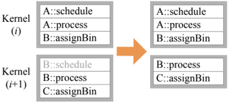
The image is a technical diagram illustrating a state transition between two computational kernels, labeled Kernel (i) and Kernel (i+1). It depicts a filtering or reassignment process where specific tasks (identified by a `Component::Task` naming convention) are removed or altered when moving from one kernel iteration to the next. The diagram uses a simple box-and-arrow flowchart style.
### Components/Axes
The diagram is composed of the following spatially arranged elements:
1. **Left Column (Source State):**
* **Top Box:** Labeled `Kernel (i)`. Contains a list of three tasks.
* **Bottom Box:** Labeled `Kernel (i+1)`. Contains a list of three tasks.
* *Positioning:* These two boxes are stacked vertically on the left side of the image.
2. **Central Element:**
* A large, solid orange arrow pointing from the left column to the right column. This indicates the direction of the process or transformation.
3. **Right Column (Resulting State):**
* **Top Box:** Unlabeled, but corresponds to the transformed state of the top-left box. Contains a list of two tasks.
* **Bottom Box:** Unlabeled, but corresponds to the transformed state of the bottom-left box. Contains a list of two tasks.
* *Positioning:* These two boxes are stacked vertically on the right side of the image, aligned with their counterparts on the left.
### Detailed Analysis
**Task Lists and Transformation:**
* **Kernel (i) - Top Box (Source):**
1. `A::schedule`
2. `A::process`
3. `B::assignBin`
* **Kernel (i) - Bottom Box (Source):**
1. `B::schedule` (This text is in a lighter gray font compared to the others).
2. `B::process`
3. `C::assignBin`
* **Transformation (via Orange Arrow):** The arrow signifies a process applied to the tasks in Kernel (i) to produce the state shown on the right.
* **Resulting State - Top Box:**
1. `A::schedule`
2. `A::process`
* **Change:** The task `B::assignBin` has been removed.
* **Resulting State - Bottom Box:**
1. `B::process`
2. `C::assignBin`
* **Change:** The task `B::schedule` (the grayed-out text) has been removed.
### Key Observations
1. **Selective Removal:** The transformation does not affect all tasks equally. It specifically removes one task from each kernel's list.
2. **Grayed-Out Text:** The task `B::schedule` in the source Kernel (i+1) is displayed in a lighter gray. This visual distinction likely indicates it is in a different state (e.g., completed, pending, invalid) prior to the transformation, which may explain its subsequent removal.
3. **Task Naming Convention:** All tasks follow the pattern `[Component Identifier]::[Task Name]`. The components involved are `A`, `B`, and `C`. The tasks are `schedule`, `process`, and `assignBin`.
4. **Spatial Consistency:** The layout is consistent, with the top and bottom boxes on each side maintaining their relative positions, making the before-and-after comparison clear.
### Interpretation
This diagram likely models a step in a parallel computing or task scheduling system, such as a GPU warp scheduler or a CPU thread pool manager. The key insight is the **selective filtering of tasks between kernel iterations**.
* **What it demonstrates:** The system is transitioning from a state where certain tasks are queued (Kernel i) to a subsequent state (Kernel i+1) where specific tasks are no longer present. The removal of `B::assignBin` from the top group and the pre-emptively grayed-out `B::schedule` from the bottom group suggests a logic where tasks associated with component `B` are being deprioritized, completed, or reallocated.
* **Relationship between elements:** The orange arrow is the critical operator. It represents the scheduling policy or execution logic that evaluates the task list in Kernel (i) and produces the refined list for Kernel (i+1). The gray text acts as a visual cue for a precondition that influences this logic.
* **Notable Pattern:** The pattern is not random removal. It appears to target specific task types (`schedule` and `assignBin`) for component `B`, while leaving `process` tasks and all tasks for components `A` and `C` intact. This could indicate a phase-based execution where scheduling and bin assignment for a particular resource (`B`) are completed in one cycle, allowing only processing to continue to the next cycle.
**In essence, the diagram visualizes a state change in a computational workflow, highlighting how a scheduler prunes or advances a task list based on component-specific rules and pre-existing task states.**