## Diagram: Body Part Dependency Modeling with Attention
### Overview
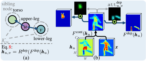
The image is a technical diagram, likely from a computer vision or machine learning research paper, illustrating a method for modeling dependencies between human body parts. It consists of two main components: (a) a conceptual graph model and (b) a corresponding neural network architecture diagram showing feature processing and attention mechanisms.
### Components/Axes
The diagram is divided into two labeled sections:
- **(a) Left Side**: A conceptual graph model.
- **(b) Right Side**: A detailed architectural flow diagram.
**Textual Elements Identified:**
1. **In Section (a):**
* Labels: "sibling node", "torso", "upper-leg", "lower-leg".
* Node identifiers: `u` (purple circle), `v` (teal circle).
* Edge label: `K_{u,v}` (dashed line).
* Equation: `Eq. 8: h_{u,v} = F^{dep}(F^{dep}(h_u))`
2. **In Section (b):**
* Input/Output Labels: `x` (input image), `h_u` (feature map), `F^{cont}(h_u)`, `F^{dep}(h_u)`.
* Process Labels: `att_{u,v}^{dep}` (attention map).
* Dimensional Annotations: `C`, `H`, `W` on the `h_u` block, indicating Channels, Height, Width.
* Visual Elements: Color-coded heatmaps (blue to red/yellow), arrows indicating data flow, and multiplication symbols (⊗) indicating element-wise multiplication or attention application.
### Detailed Analysis
**Section (a) - Conceptual Model:**
* **Structure:** A directed graph with two nodes, `u` and `v`. Node `u` is labeled "upper-leg" and node `v` is labeled "lower-leg". A dashed line labeled "sibling node" connects to node `u`, which is also associated with the "torso".
* **Relationship:** A solid arrow points from `u` to `v`, labeled `K_{u,v}`, representing a known kinematic or spatial relationship.
* **Equation:** The mathematical definition `h_{u,v} = F^{dep}(F^{dep}(h_u))` is provided. This suggests the dependency feature `h_{u,v}` between parts `u` and `v` is computed by applying a dependency function `F^{dep}` twice to the feature representation `h_u` of part `u`.
**Section (b) - Architectural Flow:**
The flow proceeds from bottom-left to top-right.
1. **Input & Initial Features:** An input image `x` (showing a person in a pose) and a feature map `h_u` (a heatmap highlighting the "upper-leg" region) are inputs. `h_u` has dimensions annotated as `C` (channels), `H` (height), `W` (width).
2. **Content Feature Path:** `h_u` is processed to produce `F^{cont}(h_u)`, a content feature map. This appears as a blue-toned heatmap.
3. **Dependency Feature Path:** `h_u` is also processed to produce `F^{dep}(h_u)`, a dependency feature map. This is a more intense heatmap with red/yellow highlights.
4. **Attention Generation:** The dependency feature `F^{dep}(h_u)` is used to generate an attention map `att_{u,v}^{dep}`. This map is shown as a small, focused green/yellow blob on a dark background, indicating a localized region of interest.
5. **Attention Application:** The attention map `att_{u,v}^{dep}` is multiplied (⊗) with the content feature `F^{cont}(h_u)`. This operation focuses the content features on the region specified by the dependency-based attention.
6. **Final Output:** The result of the multiplication is the final dependency-aware feature map `F^{dep}(h_u)` for the relationship between `u` and `v`, shown as a blue heatmap with a highlighted region corresponding to the "lower-leg".
### Key Observations
* **Spatial Grounding:** The attention map `att_{u,v}^{dep}` is positioned in the upper-middle of section (b). Its green/yellow highlight corresponds spatially to the lower-leg region in the final output map `F^{dep}(h_u)` on the far right.
* **Trend/Flow Verification:** The diagram shows a clear logical flow: from a part-specific feature (`h_u`), it computes both a general content representation and a specialized dependency representation. The latter is used to generate spatial attention, which then filters the content representation to produce a feature map for the related part (`v`).
* **Color Consistency:** The heatmap color scale (blue=low, red/yellow=high activation) is consistent across `h_u`, `F^{cont}(h_u)`, `F^{dep}(h_u)`, and the final output. The attention map uses a different (green/yellow) scale.
* **Component Isolation:** The diagram is cleanly segmented. Section (a) provides the abstract model, while section (b) details the concrete implementation using neural network operations.
### Interpretation
This diagram illustrates a **dependency-aware attention mechanism** for human pose or part analysis. The core idea is that the feature representation for one body part (e.g., upper-leg) should be used to dynamically attend to its related part (e.g., lower-leg) in the image.
* **What it demonstrates:** It shows how a model can move beyond processing body parts in isolation. By using a learned dependency function (`F^{dep}`), the model generates an attention map that predicts *where* a related part should be, based on the current part's features. This attention then refines the features to focus on the correct spatial location for the related part.
* **Relationship between elements:** The equation in (a) defines the theoretical operation. The architecture in (b) implements it: `h_u` is the input feature for part `u`. `F^{dep}(h_u)` is used to model the relationship to part `v`, which manifests as the attention map `att_{u,v}^{dep}`. This attention is applied to the content features `F^{cont}(h_u)` to produce the final output feature `F^{dep}(h_u)` that is specialized for the `u->v` relationship.
* **Significance:** This approach likely improves the model's understanding of human pose by enforcing structural constraints and relationships between parts. It allows the network to use contextual information from one body part to better locate and represent another, which is crucial for tasks like pose estimation, action recognition, or human-object interaction analysis. The "sibling node" and "torso" labels in (a) hint at a broader kinematic tree being modeled.