## Diagram: Hierarchical Body Part Processing Pipeline
### Overview
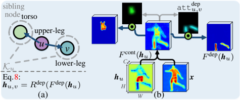
The image depicts a two-part technical diagram illustrating a hierarchical processing pipeline for body part analysis. The left section shows a sibling node structure with anatomical components, while the right section demonstrates a computational workflow involving feature extraction and transformation.
### Components/Axes
**Left Diagram (Hierarchical Structure):**
- **Nodes:**
- `torso` (central node, colored green)
- `upper-leg` (node `u`, colored purple)
- `lower-leg` (node `v`, colored blue)
- **Connections:**
- Solid line between `u` and `v` labeled `K_u`
- Dashed line connecting `torso` to `u` and `v`
- **Equation:**
- `Eq.8: h_u,v = R^dep(F^dep(h_u))`
- Positioned below the dashed line
**Right Diagram (Computational Workflow):**
- **Input:**
- Torso image (blue box with orange torso icon)
- **Processing Steps:**
1. `att_dep` (attention dependency map, green heatmap)
2. `F_cont(h_u)` (continuous feature map, yellow-green gradient)
3. `F_dep(h_u)` (dependent feature map, red-blue gradient)
- **Output:**
- Final output `x` (blue box with red/yellow figure)
- **Intermediate Components:**
- `C_s` (circular component between `F_cont` and `F_dep`)
- `h_u` (input feature vector, labeled at multiple stages)
### Detailed Analysis
**Left Diagram:**
- The sibling node structure (`torso`, `upper-leg`, `lower-leg`) suggests a hierarchical relationship where the torso acts as a parent node to the leg components.
- The equation `h_u,v = R^dep(F^dep(h_u))` implies a dependency relationship between upper and lower leg features, processed through a dependency resolution function `R^dep` applied to transformed features `F^dep`.
**Right Diagram:**
- The workflow begins with a torso image input, which undergoes attention-based dependency analysis (`att_dep`).
- Continuous features (`F_cont`) and dependent features (`F_dep`) are extracted from the input, with `F_cont` showing a smooth gradient (likely spatial features) and `F_dep` showing localized activation (likely joint-specific features).
- The circular component `C_s` appears to mediate between continuous and dependent features before producing the final output `x`.
### Key Observations
1. **Color Coding:**
- Green dominates the torso-related components (sibling node, attention map)
- Purple/blue for upper/lower leg nodes
- Red/blue gradients in dependent features suggest joint-specific activation
2. **Flow Direction:**
- Left-to-right processing in the computational workflow
- Bidirectional connections in the hierarchical structure (dashed lines)
3. **Feature Transformation:**
- `F_cont` and `F_dep` represent complementary feature types
- `R^dep` appears to resolve interdependencies between leg components
### Interpretation
This diagram illustrates a multi-stage processing pipeline for human body analysis, likely in a computer vision or biomechanical context. The hierarchical structure on the left suggests a graph-based representation of body parts, while the right diagram shows how these components are processed computationally.
The use of attention mechanisms (`att_dep`) and feature transformation functions (`F_cont`, `F_dep`) indicates a sophisticated approach to capturing both global spatial relationships (through continuous features) and localized joint-specific information (through dependent features). The final output `x` likely represents a transformed or enhanced version of the input torso image, enriched with contextual information from the leg components.
The equation `h_u,v = R^dep(F^dep(h_u))` implies that the system models interactions between upper and lower leg features, possibly to account for biomechanical constraints or movement dynamics. This could be particularly relevant in applications like gait analysis, posture recognition, or motion capture systems.
The color coding and component placement suggest a deliberate design to separate different processing stages while maintaining clear relationships between anatomical components and their computational representations.