## Lever Diagram: Weight Calculation
### Overview
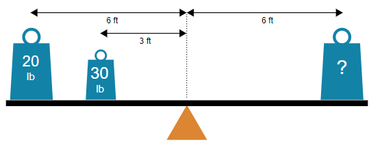
The image depicts a lever diagram with two known weights and one unknown weight. The diagram shows the distances of the weights from the fulcrum. The goal is likely to determine the unknown weight required to balance the lever.
### Components/Axes
* **Fulcrum:** Represented by an orange triangle at the center of the lever.
* **Lever:** A black horizontal line resting on the fulcrum.
* **Weights:** Three teal-colored rectangular blocks with circles on top, representing weights.
* Left weight: Labeled "20 lb"
* Middle weight: Labeled "30 lb"
* Right weight: Labeled "?"
* **Distances:**
* Distance from the fulcrum to the left weight: 6 ft
* Distance from the fulcrum to the middle weight: 3 ft
* Distance from the fulcrum to the right weight: 6 ft
### Detailed Analysis
* **Left Weight:** 20 lb, located 6 ft to the left of the fulcrum.
* **Middle Weight:** 30 lb, located 3 ft to the left of the fulcrum.
* **Right Weight:** Unknown weight (?), located 6 ft to the right of the fulcrum.
### Key Observations
The diagram illustrates a lever system where the combined moment of the two weights on the left must equal the moment of the weight on the right for the lever to be balanced.
### Interpretation
The diagram presents a statics problem involving a lever. To solve for the unknown weight, we can use the principle of moments:
(Force1 \* Distance1) + (Force2 \* Distance2) = (Force3 \* Distance3)
In this case:
(20 lb \* 6 ft) + (30 lb \* 3 ft) = (? lb \* 6 ft)
120 lb\*ft + 90 lb\*ft = (? lb \* 6 ft)
210 lb\*ft = (? lb \* 6 ft)
? lb = 210 lb\*ft / 6 ft
? lb = 35 lb
Therefore, the unknown weight should be 35 lb to balance the lever. The diagram demonstrates the relationship between force, distance, and equilibrium in a lever system.