\n
## Diagram: Lever Problem
### Overview
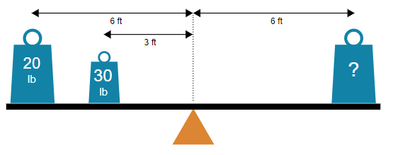
The image depicts a lever with two known weights and a third unknown weight. The diagram illustrates a physics problem related to moments and equilibrium. Distances from the fulcrum are also provided.
### Components/Axes
The diagram consists of:
* A horizontal lever arm.
* A triangular fulcrum positioned approximately in the center of the lever.
* Three rectangular blocks representing weights.
* Distance labels indicating the distance of each weight from the fulcrum.
* Weight labels indicating the weight of the first two blocks.
* A question mark within the third block, indicating an unknown weight.
The distances are labeled as follows:
* Distance from the left weight to the fulcrum: 6 ft
* Distance from the center weight to the fulcrum: 3 ft
* Distance from the right weight to the fulcrum: 6 ft
The weights are labeled as follows:
* Left weight: 20 lb
* Center weight: 30 lb
* Right weight: ? lb
### Detailed Analysis
The diagram presents a static equilibrium problem. To solve for the unknown weight, we can use the principle of moments. The sum of the clockwise moments must equal the sum of the counterclockwise moments.
* Moment due to the left weight: 20 lb * 6 ft = 120 lb-ft (counterclockwise)
* Moment due to the center weight: 30 lb * 3 ft = 90 lb-ft (clockwise)
* Let the unknown weight be 'x' lb.
* Moment due to the right weight: x lb * 6 ft = 6x lb-ft (clockwise)
For equilibrium:
120 lb-ft = 90 lb-ft + 6x lb-ft
30 lb-ft = 6x lb-ft
x = 5 lb
Therefore, the unknown weight is 5 lb.
### Key Observations
The diagram is a simple representation of a lever system. The distances and weights are clearly labeled. The placement of the fulcrum is crucial for determining the equilibrium condition. The center weight is closer to the fulcrum, requiring a smaller weight on the right side to balance the lever.
### Interpretation
The diagram demonstrates the principle of moments in physics. The moment of a force is the product of the force and the perpendicular distance from the line of action of the force to the fulcrum. For a lever to be in equilibrium, the sum of the clockwise moments must equal the sum of the counterclockwise moments. This diagram illustrates how the position of the fulcrum and the magnitudes of the weights affect the equilibrium condition. The problem is designed to test understanding of this fundamental concept. The diagram is a visual aid for solving a basic statics problem.