## Diagram: Balance Scale with Torque Equilibrium
### Overview
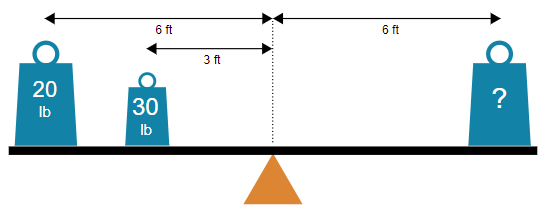
The image depicts a horizontal balance scale with three weights positioned at varying distances from the fulcrum (center pivot point). The system is in static equilibrium, with the beam balanced horizontally.
### Components/Axes
- **Fulcrum**: Central pivot point (orange triangle) labeled with a dashed vertical line.
- **Weights**:
- Left side:
- 20 lb weight positioned 6 ft left of the fulcrum.
- 30 lb weight positioned 3 ft left of the fulcrum.
- Right side:
- Unknown weight (marked with "?") positioned 6 ft right of the fulcrum.
- **Distances**:
- Arrows indicate distances from the fulcrum: 6 ft (left and right), 3 ft (left).
### Detailed Analysis
1. **Torque Calculation**:
- Left side total torque:
$ (20 \, \text{lb} \times 6 \, \text{ft}) + (30 \, \text{lb} \times 3 \, \text{ft}) = 120 \, \text{lb-ft} + 90 \, \text{lb-ft} = 210 \, \text{lb-ft} $.
- Right side torque must equal 210 lb-ft for equilibrium.
- Unknown weight: $ \frac{210 \, \text{lb-ft}}{6 \, \text{ft}} = 35 \, \text{lb} $.
2. **Spatial Grounding**:
- All weights are aligned horizontally along the beam.
- Distances are explicitly labeled with arrows pointing to the fulcrum.
### Key Observations
- The system adheres to the principle of torque equilibrium: $ \text{Torque}_{\text{left}} = \text{Torque}_{\text{right}} $.
- The unknown weight is calculated to be **35 lb** to maintain balance.
- No outliers or anomalies; the diagram explicitly shows a balanced state.
### Interpretation
This diagram demonstrates the application of rotational equilibrium in physics. The placement and magnitude of weights are inversely proportional to their distances from the fulcrum to achieve balance. The calculation confirms that the unknown weight must be **35 lb** to counteract the combined torque of the left-side weights. The diagram serves as a visual aid for understanding lever mechanics and torque distribution.