## Heatmap: Time vs. X with Contour Lines
### Overview
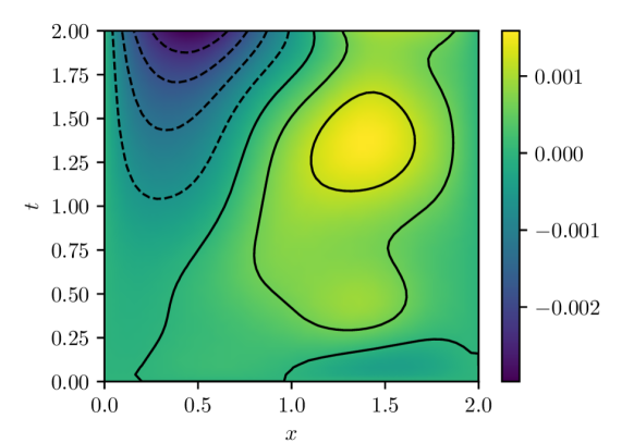
The image is a heatmap representing data over a two-dimensional space defined by the variables 'x' and 't'. The heatmap uses a color gradient to indicate the magnitude of the data, ranging from dark purple (lowest values) to bright yellow (highest values). Superimposed on the heatmap are black contour lines, both solid and dashed, indicating specific data levels.
### Components/Axes
* **X-axis:** Labeled 'x', ranges from 0.0 to 2.0 in increments of 0.5.
* **Y-axis:** Labeled 't', ranges from 0.0 to 2.0 in increments of 0.25.
* **Colorbar:** Located on the right side of the image, it represents the data values corresponding to the heatmap colors. The colorbar ranges from -0.002 (dark purple) to 0.001 (bright yellow), with 0.000 (green) in the middle.
* **Contour Lines:** Black lines overlaid on the heatmap. Solid lines represent positive values, while dashed lines represent negative values.
### Detailed Analysis
* **Heatmap Color Distribution:**
* The lower-left corner (x=0, t=0) is greenish, indicating values around -0.001.
* The upper-left corner (x=0, t=2) is dark purple, indicating values around -0.002.
* The center of the heatmap, around (x=1.5, t=1.5), is bright yellow, indicating values around 0.001.
* The lower-right corner (x=2, t=0) is greenish, indicating values around -0.001.
* **Contour Lines:**
* A dashed contour line is present in the upper-left corner, indicating a negative value region. It starts at approximately (x=0.25, t=2.0) and curves down to approximately (x=0.5, t=1.25).
* A solid contour line starts at approximately (x=0.75, t=0.0) and curves upwards, passing through approximately (x=1.0, t=0.75), then curves back down to approximately (x=1.75, t=2.0).
* Another solid contour line forms a closed loop around the yellow region, centered approximately at (x=1.5, t=1.5).
* **Specific Data Points (Approximations based on color):**
* (x=0.0, t=0.0): Value ≈ -0.001
* (x=2.0, t=2.0): Value ≈ -0.001
* (x=1.5, t=1.5): Value ≈ 0.001
* (x=0.0, t=2.0): Value ≈ -0.002
### Key Observations
* There is a clear positive peak in the center of the heatmap.
* The negative values are concentrated in the upper-left corner.
* The contour lines provide a visual representation of the data's gradient and highlight regions of constant value.
### Interpretation
The heatmap visualizes a two-dimensional function or field, where the color intensity represents the magnitude of the function at each point (x, t). The contour lines further delineate regions of equal value, providing a more detailed understanding of the function's behavior. The data suggests a localized maximum around (x=1.5, t=1.5) and a localized minimum in the upper-left corner. The relationship between x and t influences the data values, with certain combinations resulting in higher or lower magnitudes. The presence of both positive and negative values indicates that the function is not strictly positive or negative across the entire domain.