## Diagram: IBM HERMES Project Chip Implementation
### Overview
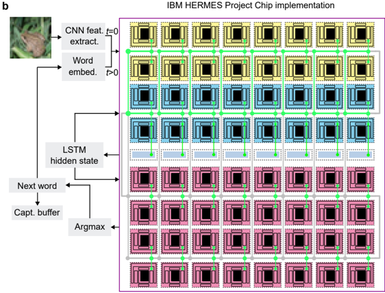
The diagram illustrates a computational architecture for the IBM HERMES Project Chip, depicting the flow of data through a neural network pipeline. It combines computer vision (CNN) and natural language processing (LSTM) components, with explicit connections between processing stages. The architecture is visualized as a grid of colored blocks connected by green lines, representing data flow.
### Components/Axes
1. **Input Stage**:
- **CNN Feature Extractor**: Top-left block (image of a frog on green foliage)
- **Word Embedding**: Adjacent to CNN block, labeled "Word embed."
2. **Processing Layers**:
- **LSTM Hidden State**: Middle section, receiving input from CNN/word embeddings
- **Next Word Prediction**: Lower section, connected to LSTM hidden state
- **Capture Buffer**: Bottom-most layer, receiving input from LSTM
3. **Output Stage**:
- **Argmax**: Final block at bottom-right, receiving input from capture buffer
4. **Color-Coded Blocks**:
- **Yellow**: Top row (CNN/word embeddings)
- **Blue**: Middle row (LSTM hidden state)
- **Pink**: Bottom row (Next word/capture buffer)
- **Green Lines**: Data flow connections between blocks
### Detailed Analysis
- **CNN Feature Extraction**: Initial processing of visual input (frog image) into feature maps
- **Word Embedding**: Conversion of visual features into semantic word representations
- **LSTM Processing**: Sequential processing of embedded words through hidden states
- **Next Word Prediction**: Generation of probability distribution over vocabulary
- **Capture Buffer**: Temporary storage of predicted words
- **Argmax Operation**: Selection of most probable next word from distribution
### Key Observations
1. **Sequential Flow**: Data progresses from visual input (top-left) to final word prediction (bottom-right)
2. **Layered Architecture**: Three distinct processing layers (CNN → LSTM → Output)
3. **Color Coding**: Visual differentiation of processing stages by color
4. **Bidirectional Connections**: Green lines show both forward and feedback connections
5. **Modular Design**: Clear separation of components with defined interfaces
### Interpretation
This architecture represents a hybrid vision-language model where:
1. **CNN** processes raw image data into feature maps
2. **Word Embeddings** bridge visual features and linguistic representations
3. **LSTM** handles temporal dependencies in sequential data
4. **Argmax** implements greedy decoding for word prediction
The design suggests an image captioning system where visual input is converted to textual output through multi-stage processing. The capture buffer likely implements beam search or similar decoding strategy, with argmax representing final word selection. The green connections indicate both feedforward and recurrent pathways typical in LSTM architectures.
No numerical data or quantitative measurements are present in the diagram. The focus is on architectural components and data flow rather than performance metrics.