## Process Diagram: Homomorphic Encryption Workflow
### Overview
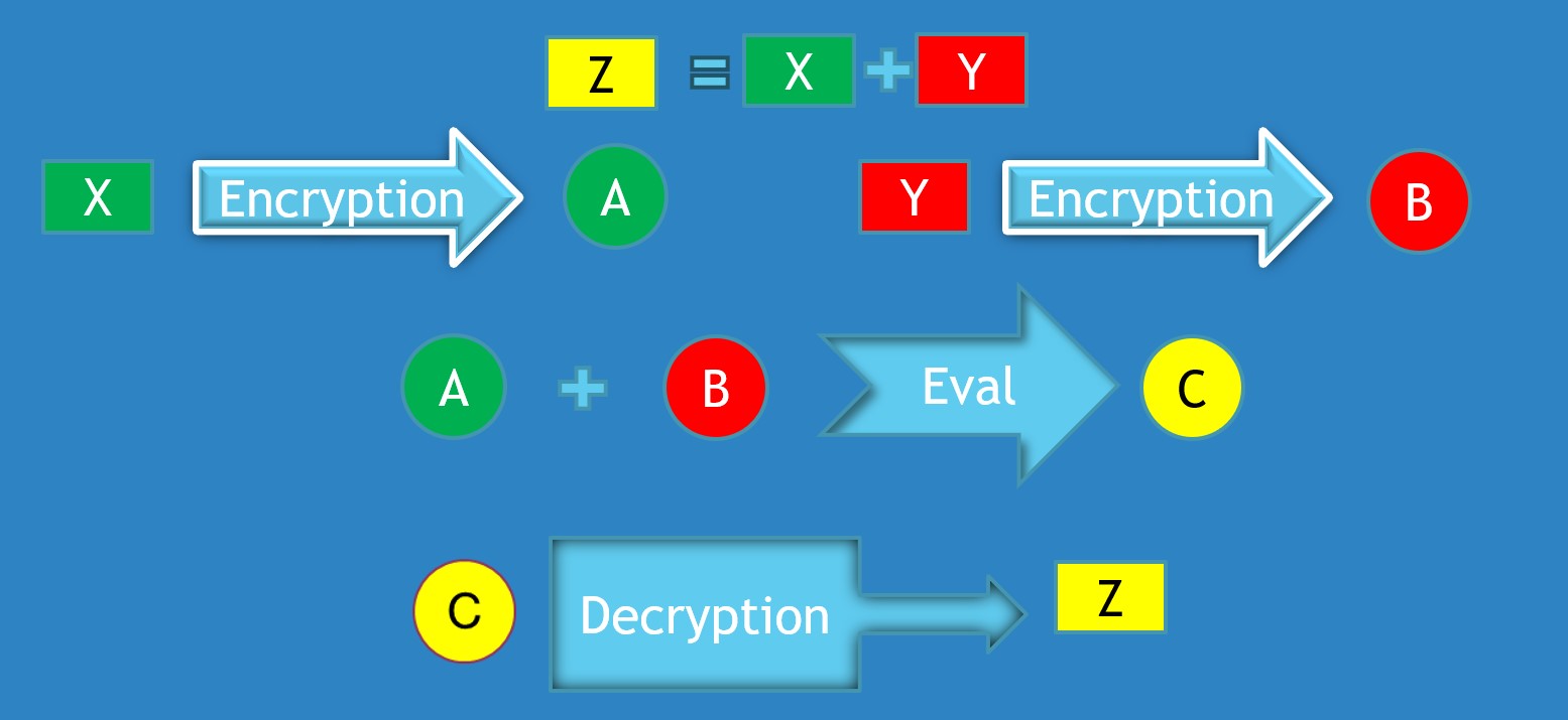
The image is a technical flowchart illustrating a cryptographic process, likely a simplified representation of homomorphic encryption. It demonstrates how two plaintext values (X and Y) can be encrypted separately, combined in their encrypted form to produce a new encrypted result (C), which, when decrypted, yields the correct result (Z) of an operation performed on the original plaintexts. The diagram uses color-coding and directional arrows to show the flow of data and transformations.
### Components/Axes
The diagram is composed of the following elements on a solid blue background:
* **Shapes & Labels:**
* **Rectangles:** Contain single-letter variables.
* Green rectangle: `X` (top-left)
* Red rectangle: `Y` (top-right)
* Yellow rectangle: `Z` (top-center, in equation; bottom-right)
* **Circles:** Contain single-letter variables representing encrypted forms.
* Green circle: `A` (center-left, after first encryption)
* Red circle: `B` (center-right, after second encryption)
* Yellow circle: `C` (center, after evaluation; bottom-left)
* **Arrows with Text:** Represent operations or processes.
* Two large, light-blue arrows pointing right, labeled `Encryption`.
* One large, light-blue arrow pointing right, labeled `Eval`.
* One large, light-blue arrow pointing right, labeled `Decryption`.
* **Mathematical Symbols:**
* An equals sign (`=`) and a plus sign (`+`) in the top equation.
* A plus sign (`+`) between the circles `A` and `B`.
* **Spatial Layout:**
* **Top Region:** Contains the defining equation `Z = X + Y`.
* **Middle Region:** Shows the parallel encryption of `X` and `Y`, followed by their combination and evaluation.
* **Bottom Region:** Shows the final decryption step.
* **Flow Direction:** The process flows generally from top to bottom and left to right, following the arrows.
### Detailed Analysis
The process can be segmented into four distinct stages:
1. **Problem Definition (Top Center):**
* A yellow rectangle labeled `Z` is shown equal to the sum of a green rectangle `X` and a red rectangle `Y`. This establishes the goal: to compute `Z` from `X` and `Y`.
2. **Parallel Encryption (Middle Left & Right):**
* **Left Path:** The green rectangle `X` is the input to an `Encryption` process (light-blue arrow). The output is a green circle labeled `A`. This indicates `A` is the ciphertext of `X`.
* **Right Path:** The red rectangle `Y` is the input to a separate `Encryption` process (light-blue arrow). The output is a red circle labeled `B`. This indicates `B` is the ciphertext of `Y`.
* **Color Consistency:** The color of the plaintext rectangle (green/red) matches the color of its corresponding ciphertext circle.
3. **Homomorphic Evaluation (Middle Center):**
* The green circle `A` and red circle `B` are shown with a plus sign (`+`) between them.
* This pair (`A + B`) is the input to an `Eval` (Evaluation) process (light-blue arrow).
* The output of the `Eval` process is a yellow circle labeled `C`. This suggests `C` is the ciphertext resulting from performing the addition operation on the ciphertexts `A` and `B`.
4. **Decryption (Bottom):**
* The yellow circle `C` is the input to a `Decryption` process (light-blue arrow).
* The output is a yellow rectangle labeled `Z`. This completes the cycle, showing that decrypting the evaluated ciphertext `C` yields the correct plaintext result `Z`.
### Key Observations
* **Color-Coding Logic:** The diagram uses a strict color scheme to track data through transformations:
* **Green:** Represents the first data stream (`X` -> `A`).
* **Red:** Represents the second data stream (`Y` -> `B`).
* **Yellow:** Represents the final result (`Z` and its intermediate encrypted form `C`).
* **Process Symmetry:** The initial encryption of `X` and `Y` is a symmetric, parallel operation.
* **Abstraction:** The `Encryption`, `Eval`, and `Decryption` arrows are abstract representations. They do not specify the cryptographic algorithms, keys, or parameters used.
* **Visual Simplicity:** The diagram simplifies a complex cryptographic concept into a clear, linear flow, making the core principle of computing on encrypted data accessible.
### Interpretation
This diagram is a pedagogical illustration of **additive homomorphic encryption**. The core concept it demonstrates is that for certain encryption schemes, it is possible to perform meaningful mathematical operations (in this case, addition) directly on ciphertexts. The result of that operation, when decrypted, matches the result of performing the same operation on the original plaintexts.
* **What it Suggests:** The data flow suggests a system where a service (e.g., a cloud server) could receive encrypted data (`A` and `B`) from two different parties, compute a function on their behalf (`Eval` to produce `C`), and return the encrypted result. The service learns nothing about the underlying plaintexts `X`, `Y`, or the result `Z`, as it only ever handles ciphertexts.
* **Relationships:** The elements are related in a strict cause-and-effect chain. The equation `Z = X + Y` defines the objective. The encryption processes create the necessary inputs (`A`, `B`) for the homomorphic operation. The `Eval` function is the crucial step that preserves the mathematical relationship in the encrypted domain. The final decryption reveals the correct outcome.
* **Notable Anomalies/Considerations:** The diagram is a high-level model. In practice, homomorphic encryption schemes are computationally intensive and often involve "noise" that grows with each operation, requiring management techniques. The `Eval` step here is a black box; in reality, it would be a specific algorithm (like an addition circuit) designed to work with the chosen encryption scheme. The perfect color alignment and linear flow omit the complexities of key management, potential errors, and the specific properties (like being "fully" or "partially" homomorphic) that a real-world scheme would have.