## Control System Diagram: Vehicle Pitch Control
### Overview
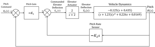
The image is a block diagram representing a closed-loop control system for vehicle pitch control. It shows the relationships between different components, including pitch command, pitch gain, elevator actuator, vehicle dynamics, and pitch rate sensor. The diagram illustrates how feedback is used to regulate the vehicle's pitch.
### Components/Axes
* **Pitch Command:** θe(s) - The desired pitch angle.
* **Pitch Gain:** -K1 - A proportional gain applied to the error signal.
* **Commanded Elevator Deflection:** δe(s) - The desired elevator deflection.
* **Elevator Actuator:** 2/(s+2) - Transfer function of the elevator actuator.
* **Elevator Deflection:** δe(s) - The actual elevator deflection.
* **Vehicle Dynamics:** -0.125(s+0.435) / ((s+1.23)(s^2 + 0.226s + 0.0169)) - Transfer function representing the vehicle's response to elevator deflection.
* **Pitch:** θ(s) - The actual pitch angle of the vehicle.
* **Pitch Rate Sensor:** -K2s - Sensor measuring the pitch rate.
### Detailed Analysis
The system operates as follows:
1. The pitch command θe(s) is compared to the feedback signal from the pitch rate sensor.
2. The error signal is multiplied by the pitch gain -K1.
3. The output of the pitch gain is compared to the feedback signal from the pitch.
4. The resulting signal is the commanded elevator deflection δe(s).
5. The elevator actuator, represented by the transfer function 2/(s+2), converts the commanded deflection into an actual elevator deflection δe(s).
6. The elevator deflection affects the vehicle dynamics, represented by the transfer function -0.125(s+0.435) / ((s+1.23)(s^2 + 0.226s + 0.0169)), resulting in a pitch angle θ(s).
7. The pitch angle is fed back to the initial comparator, and the pitch rate is measured by the pitch rate sensor and fed back to the second comparator, closing the loop.
### Key Observations
* The system uses both pitch angle and pitch rate feedback.
* The vehicle dynamics transfer function is a complex expression involving poles and zeros.
* The elevator actuator is modeled as a first-order system.
### Interpretation
This block diagram represents a closed-loop control system designed to regulate the pitch of a vehicle. The system uses feedback from both the pitch angle and pitch rate to minimize the error between the desired pitch (pitch command) and the actual pitch. The transfer functions for the elevator actuator and vehicle dynamics describe how these components respond to inputs. The gains K1 and K2 are design parameters that can be tuned to achieve desired performance characteristics, such as stability and response time. The negative signs in front of K1 and K2s indicate negative feedback, which is essential for stabilizing the system. The system appears to be designed to maintain a stable pitch angle despite disturbances or changes in the vehicle's environment.