## Control System Block Diagram: Aircraft Pitch Control System
### Overview
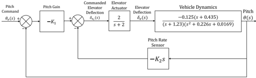
The image displays a technical block diagram representing a closed-loop control system for aircraft pitch. The diagram illustrates the signal flow from a pitch command input to the resulting pitch output, incorporating feedback loops for stabilization. It is a standard engineering schematic using blocks, arrows, and summing junctions to represent system components and their interactions.
### Components/Axes
The diagram is structured as a signal flow graph from left to right, with feedback loops returning from right to left.
**1. Input (Leftmost):**
* **Label:** `Pitch Command`
* **Symbol:** `θ_c(s)` (Theta sub c of s)
**2. First Summing Junction:**
* **Position:** Immediately after the input.
* **Inputs:** `θ_c(s)` (positive) and a feedback signal (negative, indicated by a `-` sign).
* **Output:** Error signal (not explicitly labeled).
**3. Pitch Gain Block:**
* **Label:** `Pitch Gain`
* **Transfer Function:** `-K₁` (Negative K-one)
**4. Second Summing Junction:**
* **Position:** After the Pitch Gain block.
* **Inputs:** Output from Pitch Gain (positive) and a feedback signal from the Pitch Rate Sensor (negative, indicated by a `-` sign).
* **Output Label:** `Commanded Elevator Deflection`
* **Output Symbol:** `δ_e(s)` (Delta sub e of s)
**5. Elevator Actuator Block:**
* **Label:** `Elevator Actuator`
* **Transfer Function:** `2 / (s + 2)`
* **Output Label:** `Elevator Deflection`
* **Output Symbol:** `δ_e(s)` (Same symbol as input, representing the physical deflection).
**6. Vehicle Dynamics Block:**
* **Label:** `Vehicle Dynamics`
* **Transfer Function:** `-0.125(s + 0.435) / [(s + 1.23)(s² + 0.226s + 0.0169)]`
* **Output Label:** `Pitch`
* **Output Symbol:** `θ(s)` (Theta of s)
**7. Feedback Path 1 (Inner Loop):**
* **Source:** The `Pitch` output `θ(s)`.
* **Block Label:** `Pitch Rate Sensor`
* **Transfer Function:** `-K₂s` (Negative K-two times s). This represents a derivative (rate) sensor with gain.
* **Destination:** The second summing junction (negative input).
**8. Feedback Path 2 (Outer Loop):**
* **Source:** The `Pitch` output `θ(s)`.
* **Path:** A direct line (implied by the `-` sign at the first summing junction) feeding back to the first summing junction. This represents unity negative feedback of the pitch angle.
### Detailed Analysis
* **System Type:** This is a multi-loop feedback control system. The inner loop (via the Pitch Rate Sensor) provides rate feedback (damping), while the outer loop provides position feedback (tracking).
* **Signal Flow:** `Pitch Command` → Error → `Pitch Gain` → Sum with rate feedback → `Commanded Elevator Deflection` → `Elevator Actuator` → `Elevator Deflection` → `Vehicle Dynamics` → `Pitch` Output.
* **Transfer Functions:**
* The **Elevator Actuator** is modeled as a first-order lag with a time constant of 0.5 seconds (from `2/(s+2)`).
* The **Vehicle Dynamics** is a third-order system. It has:
* A zero at `s = -0.435`.
* A real pole at `s = -1.23`.
* A pair of complex conjugate poles from the quadratic term `s² + 0.226s + 0.0169`. The natural frequency (ωₙ) is √0.0169 ≈ 0.13 rad/s, and the damping ratio (ζ) is 0.226 / (2 * 0.13) ≈ 0.87.
* The **gains** `K₁` and `K₂` are design parameters (unknown constants) that would be tuned to achieve desired performance (stability, response speed, overshoot).
### Key Observations
1. **Negative Feedback:** Both feedback loops are negative (indicated by `-` signs at summing junctions), which is essential for system stability and error correction.
2. **Nested Loops:** The architecture features a classic inner-outer loop structure. The inner loop (Pitch Rate Sensor) likely improves damping and stability margins, while the outer loop ensures the pitch angle tracks the command.
3. **Sign Conventions:** The negative signs in the `Pitch Gain (-K₁)` and `Pitch Rate Sensor (-K₂s)` blocks are critical. They work in conjunction with the negative feedback summing junctions to ensure the control actions oppose the error.
4. **Complex Vehicle Dynamics:** The vehicle dynamics transfer function indicates a potentially underdamped system (complex poles) that requires active control for satisfactory performance.
### Interpretation
This block diagram models the longitudinal (pitch) autopilot of an aircraft. The pilot or flight computer issues a `Pitch Command` (θ_c). The system's goal is to make the actual aircraft `Pitch` (θ) follow this command.
* **How it works:** Any difference between commanded and actual pitch creates an error. The `Pitch Gain` amplifies this error to generate a corrective command for the elevator. The `Pitch Rate Sensor` provides "artificial damping" by feeding back the rate of change of pitch, which helps prevent overshoot and oscillations. The `Elevator Actuator` models the physical lag in moving the control surface. The `Vehicle Dynamics` block encapsulates the complex aerodynamic response of the aircraft to elevator deflection.
* **Why it matters:** This is a fundamental representation used in control theory and aerospace engineering to analyze stability, design controllers (choose `K₁` and `K₂`), and simulate aircraft behavior before flight. The specific transfer function for Vehicle Dynamics would be derived from linearized equations of motion for a particular aircraft at a specific flight condition (e.g., speed, altitude).
* **Notable Design Choice:** The use of rate feedback (inner loop) is a standard technique to augment the natural damping of the aircraft, which might be low (as suggested by the complex poles in the vehicle dynamics). This allows for a more aggressive position gain (`K₁`) to achieve faster response without sacrificing stability.