## Block Diagram: Vehicle Pitch Control System
### Overview
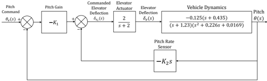
The diagram illustrates a closed-loop control system for vehicle pitch dynamics. It includes feedback mechanisms, actuator dynamics, and vehicle response characteristics. The system uses proportional and derivative gains to stabilize pitch angle (θ(s)) based on commanded inputs and sensor feedback.
### Components/Axes
1. **Input/Output Signals**:
- **Pitch Command (θ_e(s))**: Reference signal for desired pitch angle.
- **Pitch (θ(s))**: Actual pitch angle of the vehicle.
2. **Control Elements**:
- **Pitch Gain (-K₁)**: Proportional gain block amplifying the error between commanded and actual pitch.
- **Elevator Actuator**: Converts control signals into physical deflection (δ_e(s)).
- **Elevator Deflection (δ_e(s))**: Output of the actuator, modeled as a first-order lag: `2/(s + 2)`.
3. **Vehicle Dynamics**:
- Transfer function:
`[-0.125(s + 0.435)] / [(s + 1.23)(s² + 0.226s + 0.0169)]`
Represents the vehicle's response to elevator deflection.
4. **Feedback Path**:
- **Pitch Rate Sensor**: Measures pitch rate (dθ/dt), represented as `-K₂s` (derivative gain).
- Feedback loop closes around the pitch command to adjust control signals.
### Detailed Analysis
- **Signal Flow**:
1. The pitch command (θ_e(s)) is compared with the actual pitch (θ(s)) to generate an error signal.
2. The error is amplified by **-K₁** and sent to the elevator actuator.
3. The actuator's output (δ_e(s)) is filtered by `2/(s + 2)` before affecting vehicle dynamics.
4. Vehicle dynamics propagate δ_e(s) through the transfer function to produce θ(s).
5. The pitch rate sensor (-K₂s) measures the derivative of θ(s) and feeds it back to adjust the control signal, forming a closed loop.
- **Transfer Function Details**:
- **Numerator**: `-0.125(s + 0.435)` introduces a zero at **s = -0.435**, affecting high-frequency response.
- **Denominator**: Poles at **s = -1.23** (real) and roots of **s² + 0.226s + 0.0169** (complex conjugates with damping ratio ≈ 0.64 and natural frequency ≈ 0.13 rad/s). These poles dominate the system's transient response.
### Key Observations
1. **Feedback Stabilization**: The derivative feedback (-K₂s) adds damping to counteract oscillations in the vehicle dynamics.
2. **Actuator Lag**: The elevator actuator's first-order lag (`2/(s + 2)`) introduces a time delay, potentially limiting system bandwidth.
3. **Pole-Zero Interaction**: The zero at -0.435 partially cancels the slowest pole (-1.23), improving response speed but risking instability if gains are poorly tuned.
### Interpretation
This system is a **rate feedback control** design for aircraft or missile pitch stabilization. The proportional gain (-K₁) ensures tracking of the pitch command, while the derivative feedback (-K₂s) suppresses oscillations. The vehicle dynamics' slow poles (≈0.13 rad/s) suggest a sluggish open-loop response, necessitating aggressive feedback gains. However, the actuator lag and pole-zero proximity (-0.435 vs. -1.23) require careful tuning to avoid overshoot or instability. The diagram emphasizes the interplay between actuator dynamics, vehicle inertia, and feedback control in achieving stable flight attitudes.