## Diagram: Dynamic Memory Allocation for Requirements
### Overview
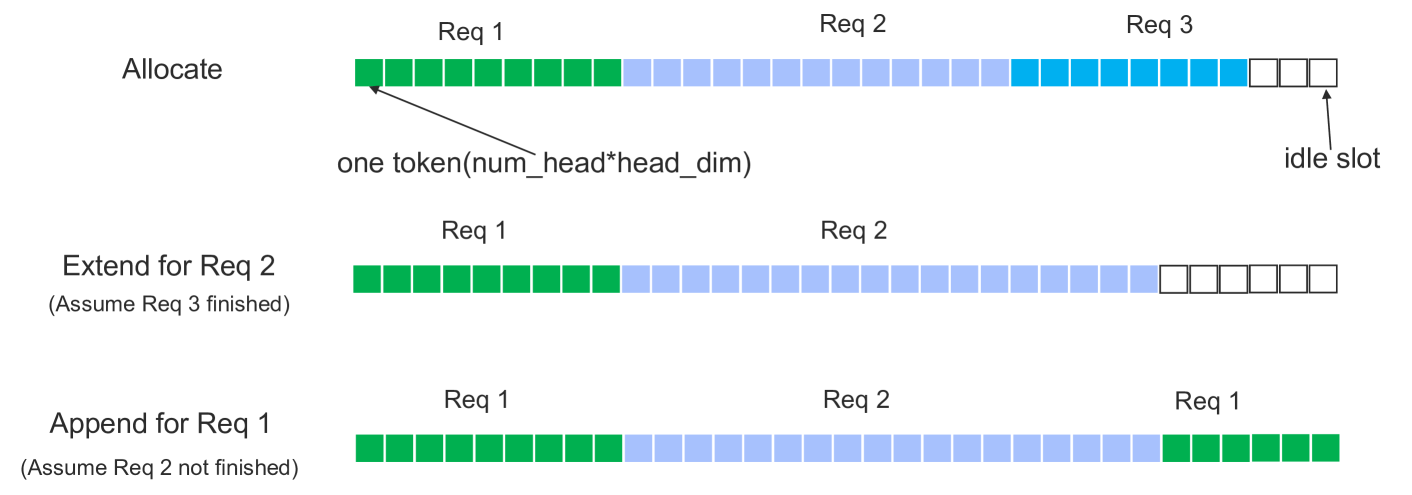
The diagram illustrates a dynamic memory allocation strategy for three requirements (Req 1, Req 2, Req 3) across three operational phases: **Allocate**, **Extend for Req 2**, and **Append for Req 1**. It uses colored blocks to represent memory tokens and idle slots, with annotations explaining allocation logic.
---
### Components/Axes
- **Y-Axis (Phases)**:
- **Allocate** (top)
- **Extend for Req 2** (middle)
- **Append for Req 1** (bottom)
- **X-Axis (Memory Blocks)**:
- Divided into segments labeled **Req 1**, **Req 2**, and **Req 3**.
- Blocks are colored:
- **Green**: Req 1
- **Blue**: Req 2
- **White**: Idle slots
- **Legend**:
- Green = Req 1
- Blue = Req 2
- White = Idle slots
- **Annotations**:
- Arrow labeled **"one token(num_head*head_dim)"** points to a green block in the **Allocate** phase.
- Arrow labeled **"idle slot"** points to a white block in the **Allocate** phase.
---
### Detailed Analysis
#### Allocate Phase
- **Req 1**: 8 green blocks (initial allocation).
- **Req 2**: 12 blue blocks (initial allocation).
- **Req 3**: 4 blue blocks (initial allocation).
- **Idle slots**: 4 white blocks (unallocated memory).
#### Extend for Req 2 Phase
- **Assumption**: Req 3 is finished (no blocks allocated).
- **Req 1**: 10 green blocks (extended from 8).
- **Req 2**: 14 blue blocks (extended from 12).
- **Idle slots**: 6 white blocks (reduced from 4).
#### Append for Req 1 Phase
- **Assumption**: Req 2 is not finished (blocks retained).
- **Req 1**: 12 green blocks (appended 2 to 10).
- **Req 2**: 14 blue blocks (unchanged).
- **Idle slots**: 4 white blocks (reduced from 6).
---
### Key Observations
1. **Initial Allocation (Allocate)**:
- Req 1 and Req 2 occupy most memory, leaving 4 idle slots.
- Req 3 shares memory with Req 2 (blue blocks).
2. **Extension for Req 2**:
- Req 1 and Req 2 grow, consuming idle slots.
- Req 3 is deallocated (no blocks).
3. **Append for Req 1**:
- Req 1 expands further, reducing idle slots.
- Req 2 remains unchanged, suggesting prioritization of Req 1.
---
### Interpretation
- **Memory Management Strategy**:
The diagram demonstrates a **dynamic allocation** approach where memory is adjusted based on requirement priorities. Req 1 and Req 2 are prioritized, while Req 3 is deprioritized or deallocated when not needed.
- **Inefficiency**:
Persistent idle slots (e.g., 4 in Allocate, 6 in Extend) indicate suboptimal memory utilization. This could reflect fragmentation or conservative allocation policies.
- **Phase Relationships**:
- **Allocate** sets the baseline.
- **Extend** modifies allocations for active requirements.
- **Append** adds to existing allocations without disrupting others.
- **Implications**:
The strategy balances flexibility (adjusting allocations) with stability (retaining Req 2 blocks). However, idle slots suggest opportunities for optimization, such as compacting memory or reallocating idle slots to active requirements.
---
### Spatial Grounding & Color Verification
- **Legend Alignment**:
- Green blocks (Req 1) match the legend.
- Blue blocks (Req 2) match the legend.
- White blocks (idle slots) match the legend.
- **Positioning**:
- Legend is placed at the top-right, adjacent to the diagram.
- Annotations are spatially grounded to specific blocks (e.g., "idle slot" points to the rightmost white block in Allocate).
---
### Final Notes
The diagram emphasizes **adaptive memory management** but highlights inefficiencies in idle slot utilization. Further analysis could explore whether idle slots are intentionally reserved for future requirements or represent fragmentation.