\n
## Diagram: Rule Application R2
### Overview
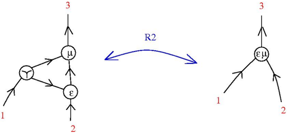
The image depicts a diagram illustrating a rule application labeled "R2". It shows a transformation from a graph on the left to a graph on the right. Both graphs consist of nodes (circles) and directed edges (arrows). Numerical labels are associated with the edges.
### Components/Axes
The diagram consists of two graphs connected by a bidirectional arrow labeled "R2".
* **Left Graph:** Contains three nodes labeled "Y", "μ", and "ε".
* **Right Graph:** Contains a single node labeled "εμ".
* **Edges:** Each edge is labeled with a number: 1, 2, and 3.
* **R2 Arrow:** A curved, bidirectional arrow labeled "R2" indicates the transformation between the two graphs.
### Detailed Analysis or Content Details
**Left Graph:**
* Node Y has two incoming edges: one labeled "1" and one from node ε.
* Node μ has two incoming edges: one from node Y and one from node ε.
* Node ε has two incoming edges: one labeled "2" and one from node Y.
* Node μ has one outgoing edge labeled "3".
**Right Graph:**
* Node εμ has two incoming edges: one labeled "1" and one labeled "2".
* Node εμ has one outgoing edge labeled "3".
The transformation R2 appears to combine nodes Y and ε into a single node εμ, while preserving the edge labels.
### Key Observations
The transformation R2 simplifies the graph by merging two nodes (Y and ε) into one (εμ). The edge labels are maintained during this transformation. The direction of the arrow suggests the transformation is reversible.
### Interpretation
This diagram likely represents a simplification or reduction rule within a formal system, possibly related to graph rewriting or algebraic manipulation. The rule R2 appears to be a combination or merging operation. The preservation of edge labels suggests that the transformation is designed to maintain certain properties or relationships within the system. The bidirectional arrow indicates that the transformation is not necessarily a one-way process, and the original state can potentially be recovered from the transformed state. The labels 1, 2, and 3 likely represent some form of input or identifier associated with the edges. Without further context, it's difficult to determine the specific meaning of these labels or the overall purpose of the transformation. However, the diagram clearly illustrates a structural change governed by the rule R2.