## Diagram: System Transformation via Rule R2
### Overview
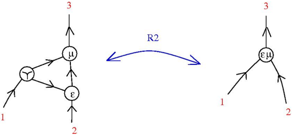
The image depicts two interconnected diagrams labeled with nodes and directional arrows. A bidirectional arrow labeled "R2" connects the left and right diagrams, suggesting a transformation or relationship between the two systems. The left diagram is more complex, while the right is simplified.
### Components/Axes
- **Left Diagram**:
- Nodes labeled: `μ`, `ε`, `1`, `2`, `3`.
- Arrows indicate directional relationships:
- `μ` → `ε` (top to bottom).
- `ε` → `1` (bottom to left).
- `ε` → `2` (bottom to right).
- `1` → `μ` (left to top).
- `2` → `μ` (right to top).
- `3` → `μ` (top to top).
- **Right Diagram**:
- Nodes labeled: `μ`, `ε`, `1`, `2`, `3`.
- Arrows indicate directional relationships:
- `μ` → `1` (top to left).
- `μ` → `2` (top to right).
- `ε` → `3` (bottom to top).
- **Connecting Element**:
- Bidirectional arrow labeled "R2" between the diagrams.
### Detailed Analysis
- **Left Diagram**:
- `μ` acts as a central hub receiving inputs from `1`, `2`, and `3`, while also sending output to `ε`.
- `ε` distributes outputs to `1` and `2`, with `1` and `2` feeding back into `μ`.
- `3` directly influences `μ` without intermediate steps.
- **Right Diagram**:
- `μ` directly controls `1` and `2`, bypassing `ε`.
- `ε` directly influences `3`, which feeds into `μ`.
- **R2 Relationship**:
- The bidirectional arrow implies a reversible transformation or equivalence between the two systems under rule R2.
### Key Observations
1. **Complexity Reduction**: The right diagram simplifies the left by removing intermediate steps (e.g., `ε` is no longer a hub for `1` and `2`).
2. **Central Role of `μ`**: In both diagrams, `μ` is a critical node, acting as a central processor or controller.
3. **Bidirectional R2**: The reversible nature of R2 suggests the transformation can be applied in both directions, preserving system integrity.
### Interpretation
The diagrams likely represent a system where rule R2 enables simplification or optimization. The left diagram may model a detailed, multi-step process, while the right diagram reflects a streamlined version. The preservation of `μ` and `ε` across both diagrams indicates these components are fundamental to the system’s functionality. The bidirectional R2 arrow implies that the transformation is not one-way, allowing for dynamic adjustments between complexity and simplicity. This could relate to computational models, workflow optimization, or theoretical frameworks where rules govern state transitions.